CORE GOTECH TIP · FROM THIS LESSON
Name the job before choosing a test.
In the horn diagram, trace what does the work and what controls it.
Start with the job, then find the load →
GOTECH STUDY GUIDE · LESSON 01
Turn a busy diagram into a story you can explain: what does the work, what controls it, and what changes when it is commanded on.
CORE GOTECH TIP · FROM THIS LESSON
In the horn diagram, trace what does the work and what controls it.
Start with the job, then find the load →GOTECH TIP · FROM THIS LESSON
The overlay identifies a role; the depicted switch state still matters.
The overlay is a teaching aid →Build the circuit model before interpreting symptoms or measurements. Identify the load, its paths and the state the diagram represents.
WAY OF THINKING
What are we actually trying to establish?
What components, circuits, networks or relationships matter?
What did we actually observe, and what are we inferring?
What does this measurement, source or test establish, and what remains unknown?
What additional evidence would reduce uncertainty the most? Choose a check that helps distinguish the remaining explanations.
Do not turn a plausible explanation into a confirmed fact.
Before you start You should recognize power, ground, a switch and a load. Open Foundations if those terms are new. Foundations ↗
01 · MAKE A PREDICTION
You have a horn diagram and a horn that does not work. Before choosing a meter point, can you explain how the drawing says the horn should operate? Keep your answer in mind as you study the example.
Try the reasoning checks →FROM THE ORIGINAL LESSON
The original lesson uses an Impala horn schematic to show how the drawing separates supply, control and ground. This is a diagram study, not a recorded repair.
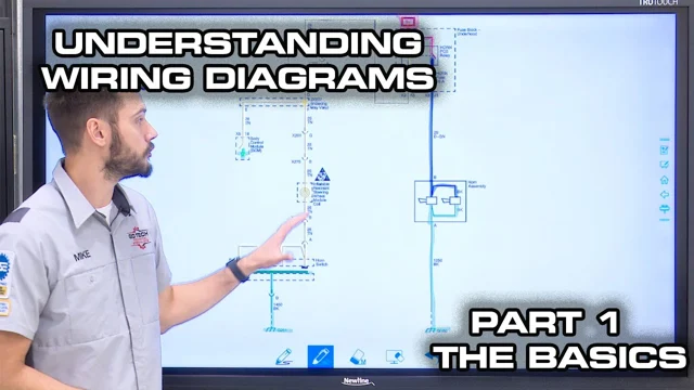
Video loads only when you choose to play.
YouTube connects only when you choose to play.
Watch on YouTube ↗ · How To Read, Understand, And Use A Wiring Diagram - Part 1 - The Basics
Watch straight through, or use the source moments below to revisit a specific explanation.
FROM THE ORIGINAL LESSON
In the instructor's 2008 Impala example, the horns do the work. The relay and its control circuit help determine when they receive power. Naming those roles gives you a starting point before you follow every line on the page.
Pause and name the load, the switching device and the command path in the instructor's drawing.
The presenter introduces rest-state conventions as rules of thumb, then traces how a command changes the relay-controlled horn circuit. The useful comparison is between the state drawn and the state being explained. A convention is a starting assumption to check against the actual diagram legend.
Which part of the explanation changes when the horn is commanded, and which connections remain the same?
The added colors classify roles such as constant power and switched ground. They are not the vehicle's physical wire colors. The next lesson also qualifies the overlay: a switched-ground label is not a promise of a particular meter reading in every switch state.
When you see a colored line, ask whether you are reading an annotation, a physical wire identification or an actual measurement.
The instructor calls attention to partial component outlines, splices and an option-dependent branch. Those details explain why the visible sheet is not always the whole component or every vehicle configuration. Follow the relevant reference and equipment context before treating a branch as part of your example.
Why it matters You can trace a line correctly and still explain the wrong configuration.
Identify one place where the source drawing sends you beyond the immediate load-and-switch picture.
Keep this example in scope The Impala drawing is the teaching example. No reproduced connector pinout, live testing instruction or completed repair is established here.
GO DEEPER
These reviewed explanations draw on their own source examples. Keep each explanation within its stated scope.
When studying a source reading, record its system/branch, test point and measurement reference, operating state and connection state. Mark any missing condition unknown before comparing it with an expected result.
Review the foundations →Educational reading of the cited source examples only. Educational treatment of the cited source cases only. No live-vehicle instruction.
Technician review pending. These explanations do not prescribe a vehicle-specific test or confirm a repair.
Use three labels in your notes: given in the source, inferred by the presenter, and still unknown. Leave missing details open.
What one voltage reading leaves unknown →Educational reading of the cited source examples only. Educational treatment of the cited source cases only. No live-vehicle instruction.
Technician review pending. These explanations do not prescribe a vehicle-specific test or confirm a repair.
FOLLOW THE REASONING
How does the command lead to the horns receiving power in this example?
The instructor identifies the horns, relay and control components, then follows the relevant connections and option branch.
Distinguish the path doing the work from the path controlling the relay. Explain the change in state before proposing a measurement.
This is a diagram explanation. The source does not supply a failed customer horn, a performed diagnostic test or a verified repair.
PRACTICE IT
Choose an answer, then compare the explanation. These checks help you study; they are not a technician certification.
0 of 3 questions compared
The overlay explains a circuit role. Terminal selection still needs the applicable wire and connector information.
Yes. This preserves the distinction between the annotation and electrical behavior. Lesson 2 develops it further.
The state still matters. A circuit-role label is not a measured or state-independent expected value.
Yes. Build the relationship model first. An unlabeled example still lets you distinguish roles without inventing a fault or a vehicle test.
The load matters, but its place in the drawing alone does not justify a first test. Map the control and operating state before selecting one.
That is a relevant relationship, but without the complaint and state it is not yet a justified test priority. Map the complete question first.
A prediction from the drawing still needs vehicle observations; no live fault or repair is supplied here.
The symbols help build the model. They do not by themselves supply the question, state or all application-specific test information.
Yes. That is valuable learning without turning a drawing exercise into repair evidence.
06 · MAKE IT YOURS
This note stays in this open page. It is not sent, graded or saved; copy it before leaving if you want to keep it.
KEEP THIS
Locate the load. Explain its control. Name the state. Then decide what question a test should answer.
Download this lesson’s study notes ↓Source-linked educational composition for owner review. Technician review is pending.
The Impala drawing is the teaching example. No reproduced connector pinout, live testing instruction or completed repair is established here.
Timestamp links identify supporting passages. They do not independently verify every source diagram or establish a procedure for another vehicle.
APPLY IT
Use the evidence worksheet to describe a source diagram: the load, the relevant paths, the shown state and the question still open. Ask GoTech about the reviewed diagram concepts; it does not identify a fault on your vehicle.
KEEP BUILDING
Lesson 2 challenges a tempting shortcut: reading the instructor's colors as though they were a meter display.
Mark studied & continue →Saves your place on this device. Your answers and written note are not saved.
Optional. No written response is collected.