CORE GOTECH TIP · FROM THIS LESSON
Separate what is shown from what you infer.
The coil explanation does not supply the missing internal schematic.
Keep an inferred switch visibly inferred →
GOTECH STUDY GUIDE · LESSON 02
Learn to separate what a wiring diagram shows from what you infer—and recognize when a measurement still leaves the question open.
CORE GOTECH TIP · FROM THIS LESSON
The coil explanation does not supply the missing internal schematic.
Keep an inferred switch visibly inferred →GOTECH TIP · FROM THIS LESSON
Keep the hypothetical coil question paired with its debrief.
Do not let the quiz force a false choice →A diagram answers some questions and leaves others dependent on another page, a stated condition or an application-specific fact. Name what is missing before filling it in.
WAY OF THINKING
What are we actually trying to establish?
What components, circuits, networks or relationships matter?
What did we actually observe, and what are we inferring?
What does this measurement, source or test establish, and what remains unknown?
What additional evidence would reduce uncertainty the most? Choose a check that helps distinguish the remaining explanations.
Do not turn a plausible explanation into a confirmed fact.
Before you start Start with Lesson 1's load, control path and state distinction. This lesson revisits the horn example before moving to a coil circuit. Foundations ↗
01 · MAKE A PREDICTION
The diagram labels a path switched ground. A learner decides that voltage there must mean a fault. What information has that learner skipped? This lesson makes that shortcut visible.
Try the reasoning checks →FROM THE ORIGINAL LESSON
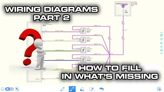
The original lesson moves from a horn circuit and connector references to a Taurus coil drawing and a hypothetical voltage question. Its quiz stays paired with Lesson 3's debrief.
Video loads only when you choose to play.
YouTube connects only when you choose to play.
Watch on YouTube ↗ · Wiring Diagrams - Read Wire Color / Connector Pin Location + Learn How To Read What ISN'T Written
Watch straight through, or use the source moments below to revisit a specific explanation.
FROM THE ORIGINAL LESSON
The instructor revisits the horn circuit with its switch open. In that illustrated condition, a voltage reading can be explained through the relay winding on a path labeled switched ground. The first lesson's colors describe roles; they do not give you a meter-reading map.
Why it matters A surprising reading is only surprising relative to an expectation. First check where that expectation came from.
Explain why the phrase switched ground is not enough to predict a reading in the open-switch example.
The presenter uses connector identity and pinout references to resolve ambiguous wire colors. Connector face orientation and the relevant legend matter. He also calls attention to a warning near the clock-spring and airbag area rather than treating it as decorative text.
Why it matters Recognizing a color does not verify the physical point or the precautions that apply to it.
What reference would you need to confirm a connector view before identifying a terminal?
In the Taurus coil example, the drawing does not show every internal PCM detail. The instructor uses the shown supply and his explanation of coil operation to infer ground-side switching. He acknowledges that some missing internals still require more information or testing.
Sort the instructor's explanation into three columns: shown on the drawing, inferred from operation, and still unknown.
The source ends with a hypothetical 12.3 V reading in a key-on, engine-off coil-circuit scenario. Two claims compete: a short to power, or a healthy primary circuit. The following lesson explains why the provided reading alone does not establish either claim.
Before opening the next lesson, write what was actually supplied and what each proposed verdict adds to it.
Keep this example in scope The voltage is a hypothetical classroom premise. Exact terminal identity, connector orientation and vehicle-specific precautions are not supplied as instructions. The debrief is included from Lesson 3 so the quiz does not teach a false verdict.
GO DEEPER
These reviewed explanations draw on their own source examples. Keep each explanation within its stated scope.
When studying a source reading, record its system/branch, test point and measurement reference, operating state and connection state. Mark any missing condition unknown before comparing it with an expected result.
Review the foundations →Educational reading of the cited source examples only. Educational treatment of the cited source cases only. No live-vehicle instruction.
Technician review pending. These explanations do not prescribe a vehicle-specific test or confirm a repair.
W3 explains that this given reading alone neither settles short-to-power nor verifies operating primary-circuit health. Retain the hypothetical premise and its reference/state.
Read the voltage reference →Educational reading of the cited source examples only. Educational treatment of the cited source cases only. No live-vehicle instruction.
Technician review pending. These explanations do not prescribe a vehicle-specific test or confirm a repair.
FOLLOW THE REASONING
A classroom coil-circuit diagram, a stated key/engine condition, a measurement reference and a hypothetical voltage reading.
A proposed explanation of internal switching that the drawing itself does not fully display.
The reading alone does not identify a short or demonstrate healthy operating behavior of the primary circuit.
What additional evidence would distinguish the competing explanations? Keep that question for the source's debrief in Lesson 3.
PRACTICE IT
Choose an answer, then compare the explanation. These checks help you study; they are not a technician certification.
0 of 3 questions compared
The open-switch and winding context can explain the observation. That context belongs before the fault interpretation.
Yes. You are interpreting the cited circuit, rather than treating a teaching annotation as measured data.
Explaining this voltage is narrower than demonstrating operation. The lesson does not supply that operating result.
A consistent explanation is not the missing internal schematic. Record the inference separately from the supplied drawing.
Yes. The sketch can help explain a relationship while its internal details remain unverified. Another source is needed before treating them as documented.
The sketch does not establish terminal identity or an appropriate reading. Obtain the applicable connector and circuit information first.
Yes. The following lesson explains why the observation fits more than one possibility and does not prove operating health.
Available voltage in this hypothetical state does not demonstrate primary-circuit behavior in operation.
The circuit state supplies another explanation. Location alone does not distinguish the alternatives.
06 · MAKE IT YOURS
This note stays in this open page. It is not sent, graded or saved; copy it before leaving if you want to keep it.
KEEP THIS
A diagram label, a plausible explanation and a measurement are different kinds of evidence. Keep them separate.
Download this lesson’s study notes ↓Source-linked educational composition for owner review. Technician review is pending.
The voltage is a hypothetical classroom premise. Exact terminal identity, connector orientation and vehicle-specific precautions are not supplied as instructions. The debrief is included from Lesson 3 so the quiz does not teach a false verdict.
Timestamp links identify supporting passages. They do not independently verify every source diagram or establish a procedure for another vehicle.
APPLY IT
Use the voltage reference to compare what the source gives with what it leaves unknown. Ask GoTech about the reviewed concept, keeping the source example and its conditions in view.
KEEP BUILDING
Lesson 3 debriefs the quiz, then applies the same discipline to two different blower-control designs.
Mark studied & continue →Saves your place on this device. Your answers and written note are not saved.
Optional. No written response is collected.