
GoTech Tips
CORE GOTECH TIP · FROM THIS LESSON
What else did that disconnection change?
The module may be out of the picture, but so may the wiring beyond it or part of the termination. Look at the whole change.
Look at the wiring examples →More GoTech tips · 1
GOTECH TIP · FROM THIS LESSON
Separate scan access from communication between modules.
Use the Jetta story to keep those questions distinct.
A scan-access complaint can be a different path →Same disconnection. Different consequences.
Before unplugging a module, trace what else that connection carries. These two arrangements show why the result can mean different things.
Branch at a junction
Wiring through a module connection
Also check termination. Either disconnection may remove termination needed by the remaining network. See why termination changes the result →
Conceptual arrangements from GoTech’s wiring lesson. Paired lines represent CAN H and CAN L; dashed lines mark the disconnected path. Not a vehicle wiring diagram. Termination is omitted so the wiring paths are easier to compare.
PRACTICE IT
Try one before you move on
Make your choice, then compare it with the explanation.
0 of 3 questions compared
Read the full explanation
Correct. Two wires can enter and two can continue the same CAN pair. Trace the actual path before deciding there are two networks.
The cited harness arrangement already offers another explanation: two ends of one path. Wire count alone cannot select protocols.
Redundancy is not established by four wires. The connector’s pass-through role and actual continuity need to be understood.
ONE MORE PART OF THE PICTURE
What does termination do?
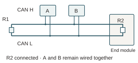
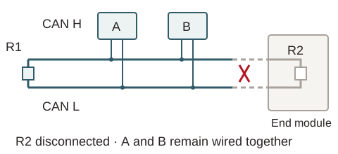
When a signal reaches the end of a transmission line, reflections can interfere with communication. Termination helps control those reflections. The video compares the terminating resistors to catchers at the ends of the illustrated network.
Both terminations connected
End module disconnected
The wiring path
Which modules are still physically connected after the change?
The termination
Did the same change remove termination that the connected section needs?
Both questions matter. A change in communication after unplugging something doesn't identify a bad module by itself.
Watch the termination explanation · 24:00
Concept explanation only. Use the actual wiring and service information for test points, power state and expected values.
Conceptual two-end termination example. Resistors bridge CAN H and CAN L; module electronics are not series loads. The actual vehicle may use a different arrangement.
FROM THE ORIGINAL LESSON
Read the wiring before interpreting the test
Does the network diagram show the physical wiring route?
A simple bus drawing does not show every connector or the route through the harness. Trace where the CAN pair continues before opening a connection. In the pass-through example, wiring continues through the module connection; the CAN transceivers are not electrically connected in series.
Check your thinking
In the source example, what would you need to confirm about the physical path before interpreting a disconnected connector?
What changes when you unplug a module?
At the illustrated junction, opening one branch leaves the other wiring paths joined. In the pass-through example, unplugging the module can also disconnect the network beyond it. The Subaru example combines junctions and direct splices: trace the segment you are testing rather than assigning one layout to the whole car.
Check your thinking
Compare the junction and pass-through examples. What remains connected in each?
Why does CAN bus termination matter during isolation?
The wiring can still be connected while the termination has changed. In the video's isolation example, account for both before deciding what the loss or return of communication tells you.
Check your thinking
Before interpreting the source's isolation example, list which wiring and termination remain in the connected portion.
The car runs, but the scan tool cannot connect—why?
In GoTech’s Jetta case, the car ran but the emissions-test equipment could not communicate. Its K-line diagnostic-access path was distinct from the CAN communication between modules. Identify whether the complaint concerns module communication, the scan-access route or an access restriction before treating them as the same fault.
Check your thinking
What are you trying to distinguish: module-to-module communication, the scan-access route, or permission to use that route?
Keep this example in scope No connector-disconnection sequence, resistor value, universal waveform threshold or current gateway-access policy is prescribed. Physical diagrams and application-specific details remain subject to verification.
PUT IT TO WORK
Two more questions
Use the case details above. Pick an answer, then check the reasoning.
Read the full explanation
The change also affected the network beyond the connection. A different response cannot isolate the module by itself.
Trace the paths that remain and any termination removed. Then interpret the scan response in that new configuration.
The scan tool is unchanged, but the network being tested is different. Account for that difference before drawing a conclusion.
Read the full explanation
A running engine is compatible with an access-path problem. It does not identify the tool as the cause.
The source case teaches why those routes must be distinguished rather than assumed identical.
Yes. The case teaches path identification, without establishing a completed repair or a particular failed component.
FROM THE ORIGINAL LESSON
Watch the original GoTech video
The original lesson compares junction and harness arrangements, then uses the recalled Jetta case to distinguish diagnostic access from module communication.
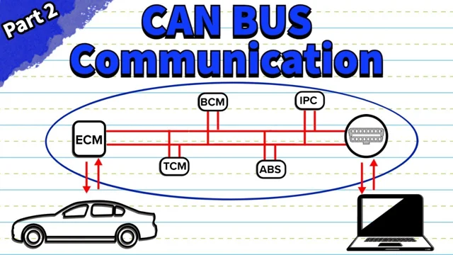
Video loads only when you choose to play.
YouTube connects only when you choose to play.
Watch on YouTube ↗ · CAN Bus Wiring and Protocol Explained (Part 2)
Watch the full video, or use the timestamp links beside each explanation to jump to that moment.
KEEP THIS
Before judging a changed response, account for the wiring path and termination that changed along with it.
Explain it back · optional
This note stays in this open page. It is not sent, graded or saved; copy it before leaving if you want to keep it.
Review your explanation
- Did I name the source example and the relevant conditions?
- Did I separate the observation from my interpretation?
- Did I say what the evidence still does not establish?
Study sheet · read or print
GOTECH · CAN PART 2 OF 3 · STUDY SHEET
CAN bus wiring explained
Before we unplug anything, let's see what stays connected. An isolation result only makes sense when we know what changed with it.
Three GoTech tips
- Follow the wiring before judging the result. Compare a branch off a junction with a connection that carries the network onward. Opening them doesn't necessarily leave the same path.
- Account for the termination too. A connection change can remove termination along with a module. Include that change when you interpret the response.
- Identify the network you're testing. A protocol name alone doesn't show the physical layout. Use the applicable diagram and test conditions.
Read the two layout examples
- A branch off a junction
- Trace which other paths stay connected when that branch opens.
- An onward connection
- Trace what lies beyond the opening. Losing several responses does not, by itself, identify one failed module.
What this does not establish
These are conceptual layouts, not instructions to disconnect a particular vehicle. They do not supply universal resistance limits, connector pins or a substitution procedure.
Your working notes
Which wiring paths changed when the connection opened?
Did termination change too? What does that let you conclude?
Go back to the source
Lesson: https://gotech.com/learn/can-bus/topology-and-protocol/
Written from GoTech's original video; these notes paraphrase the explanation. Technician review and independent verification of source diagrams remain pending.
Next: follow the Ascent investigation
Part 3 puts the ideas together on a no-crank case. Watch how the diagram changes the question.
Mark studied & continue →Saves your place on this device. Your answers and written note are not saved.
Source, scope & review
GoTech’s written companion to the original demonstration. Source moments support the case observations; the learning prompts are GoTech editorial guidance.
No connector-disconnection sequence, resistor value, universal waveform threshold or current gateway-access policy is prescribed. Physical diagrams and application-specific details remain subject to verification.
Timestamp links identify supporting passages. They do not independently verify every source diagram or establish a procedure for another vehicle.
Additional source moments
- CAN Bus Communication Explained (Part 1) · 00:40–03:35
- CAN Bus Communication Explained (Part 1) · 08:00–10:55
- CAN Bus Communication Explained (Part 1) · 15:25–18:05
- CAN Bus Communication Explained (Part 1) · 30:00–32:50
- CAN Bus Troubleshooting and Diagnosis Explained (Part 3) · 08:20–15:25
- CAN Bus Troubleshooting and Diagnosis Explained (Part 3) · 18:05–19:05
- CAN Bus Troubleshooting and Diagnosis Explained (Part 3) · 20:15–22:00
- CAN Bus Troubleshooting and Diagnosis Explained (Part 3) · 24:20–27:35