
GoTech Tips
CORE GOTECH TIP · FROM THIS LESSON
Write down exactly what came back.
Which module answered, and what changed just before it did? Those two details make the result useful to the next technician.
Compare recovery with confirmation →More GoTech tips · 1
GOTECH TIP · FROM THIS LESSON
Revisit the expectation before rejecting the reading.
The Ascent interpretation changes after branch identification.
The observation stays; its interpretation changes →SUBARU ASCENT · NO-CRANK CASE
What made us look again?
Module scan · manual identification
Body unit and combination meter respond. ECM, TCM, ABS and EyeSight do not during this scan.
The fault is not a loss of every communication path.
05:00–08:15 ↗Diagnostic port · initial resistance check
The first interpretation changes after the diagram identifies a separate access branch.
The expected result must match the branch being measured.
20:15–22:00 ↗
PRACTICE IT
Now check the reasoning
Use the two observations above, then compare your answer.
0 of 3 questions compared
Read the full explanation
The branch and service-information review changes the applicable expectation; a later response cannot retroactively verify the assumption.
Yes. The reading must be judged in the arrangement that produced it.
Moving branches can change the relevant arrangement. The source identifies that difference before reinterpreting the result.
Follow the investigation
| Location / connection state | Observation | What it means | Next question |
|---|---|---|---|
Main CAN · before and after body-unit disconnection 41:35–42:25 ▶ | The meter shows 116.5 Ω before disconnection, then O.L. after the body-unit connection is opened. | The measured resistance path depended on the body-unit connection. The expected second termination path is still missing from this measurement. | Is the missing path in the wiring toward the ECM, or at the ECM end? |
ECM end · module disconnected, harness-side check 52:00–53:55 ▶ | With the ECM disconnected, the harness-side meter display shows 114.2 Ω back toward the body unit. | That resistance path is still present from the ECM end. Together with the earlier comparison, this focuses the investigation on the ECM end. | Will the previously silent modules answer if the missing termination is temporarily restored? |
Temporary substitution · scan repeated 55:30–56:40 ▶ | The transmission module, ABS and HVAC respond during the temporary substitution shown at the end of the video. | Restoring termination changes the communication result. It supports the diagnosis, but does not show a completed repair. | Replacement, engine start and final network/road checks are not established here. |
The display reads O.L. after disconnection, although the narration says “zero resistance.” Read the meter clarification →
All case source moments
FROM THE ORIGINAL LESSON
Look closer at a step
Which modules communicate—and which do not?
Which modules communicate—and which do not?
The Ascent would not crank, yet some accessories and modules still responded. Manual identification and targeted checks produced a useful split: the body unit and combination meter answered; the ECM, TCM, ABS and EyeSight did not during the reported scan. Match that pattern to the diagram before choosing a suspect.
Check your thinking
Keep two columns while watching: reported responding modules and reported nonresponding modules. Do not reconstruct exact DTCs from unclear captions.
Why did the diagnostic-port reading need a second look?
Why did the diagnostic-port reading need a second look?
The initial diagnostic-port resistance reading was judged against a familiar expectation. The diagram then identified a separate diagnostic-port/body-unit branch, changing what that reading meant. Starting a scan conversation later produced activity on this access path. Neither observation cleared the main CAN network.
Check your thinking
Write the original interpretation and the information that changed it. Which fact changed: the reported observation, or the expectation used to judge it?
How did the investigation narrow to the main CAN network?
How did the investigation narrow to the main CAN network?
The diagram separates diagnostic access, body CAN and main CAN. The nonresponding group points the investigation toward main CAN; later comparisons narrow suspicion toward the ECM end. Record the connection state with each finding: a battery or module disconnection can also clear an intermittent condition.
Check your thinking
At each new observation, name the branch and connection state before carrying its interpretation forward.
What does O.L. mean in this comparison?
What does O.L. mean in this comparison?
At 41:40 the display shows 116.5 Ω. At 42:05 it shows O.L. on the resistance range after the body-unit connection is opened. In this comparison, that is an open/out-of-range reading, not 0 Ω. The resistance path that was visible before disconnection is no longer measured.
Check your thinking
Which path disappeared when the connection opened? Keep that observation separate from deciding whether the wiring or the ECM caused the missing second path.
What did the final test establish?
What did the final test establish?
The transmission module, ABS and HVAC answer during temporary substitution. GoTech identifies the ECM end as the suspect; the extent of internal damage is not demonstrated. The video ends before ECM replacement, a successful start or a completed post-repair check.
Check your thinking
Finish two separate notes: the source reports…; final confirmation would still need evidence of…
Keep this example in scope The readings describe this recorded case and its connection states. Use vehicle-specific service information for connector identification, test conditions and specifications. The temporary substitution is shown as part of the investigation, not a repair.
PUT IT TO WORK
Two more questions
Use the case details above. Pick an answer, then check the reasoning.
Read the full explanation
The resistance path seen before disconnection depended on that connection. The next check must distinguish the remaining wiring path from the ECM end.
O.L. is the open/out-of-range indication shown here; it is not a zero-ohm reading.
This comparison narrows the search. The harness-side check at the ECM end supplies the next piece of evidence.
Read the full explanation
A module answering does not demonstrate that the engine now starts. The original complaint needs its own recheck.
The reported responses apply to the modules checked under that condition. They do not establish the health of every branch.
Record what changed and which modules responded. A completed repair still needs a recheck of the original complaint and applicable final checks.
FROM THE ORIGINAL LESSON
Watch the original GoTech video
The original Ascent investigation shows the presenter changing the question as evidence develops. Follow both what changes and the final confirmation the source does not supply.
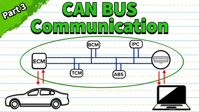
Video loads only when you choose to play.
YouTube connects only when you choose to play.
Watch on YouTube ↗ · CAN Bus Troubleshooting and Diagnosis Explained (Part 3)
Watch the full video, or use the timestamp links beside each explanation to jump to that moment.
KEEP THIS
Write down which module answered and what changed just before it did. Keep that result separate from a confirmed repair.
Explain it back · optional
This note stays in this open page. It is not sent, graded or saved; copy it before leaving if you want to keep it.
Review your explanation
- Did I name the source example and the relevant conditions?
- Did I separate the observation from my interpretation?
- Did I say what the evidence still does not establish?
Study sheet · read or print
GOTECH · CAN PART 3 OF 3 · STUDY SHEET
CAN bus diagnosis: the Subaru Ascent case
Write down what changed and what made it change. A module answering again is useful evidence. The completed repair still needs its own check.
Three GoTech tips
- List who answered—and who didn't. The body unit and combination meter responded during the reported scan. ECM, TCM, ABS and EyeSight did not.
- Match the reading to the branch. The diagram changed the interpretation of the diagnostic-port reading by identifying a separate access branch.
- Communication returns. The transmission module, ABS and HVAC answer during temporary substitution. Final repair confirmation is not shown.
The case in three steps
- Start with the response pattern
- Some modules answer. The task is to identify the network involved in the nonresponding group.
- Revisit the first interpretation
- The diagnostic-port branch isn't the same as the main network under investigation.
- Record the temporary recovery
- Communication returns. The transmission module, ABS and HVAC answer during temporary substitution. Final repair confirmation is not shown.
What this does not establish
The case shows 116.5 Ω changing to O.L., then 114.2 Ω from the ECM harness side. These are case observations, not specifications. Connector identities and a completed repair are not independently established here.
Your working notes
Observation: what did the test actually show?
Interpretation: which path does that support?
Next check: what is still unknown?
Repair check: was the original complaint resolved?
Go back to the source
Lesson: https://gotech.com/learn/can-bus/reasoning-through-the-ascent-case/
Original video displays checked October 30, 2026. Vehicle-specific connector identities and service procedures require their own verification.
Next: build your evidence worksheet
Try the same approach on another source case: what happened, what it supports and what still needs checking.
Mark studied & continue →Saves your place on this device. Your answers and written note are not saved.
Source, scope & review
Meter displays at 41:40, 42:05 and 52:15 were checked against the original video on October 30, 2026. Connector pin identities and the complete vehicle-specific wiring diagram have not been independently verified.
GoTech’s written companion to the original demonstration. Source moments support the case observations; the learning prompts are GoTech editorial guidance.
The readings describe this recorded case and its connection states. Use vehicle-specific service information for connector identification, test conditions and specifications. The temporary substitution is shown as part of the investigation, not a repair.
Timestamp links identify supporting passages. They do not independently verify every source diagram or establish a procedure for another vehicle.
Additional source moments
- CAN Bus Communication Explained (Part 1) · 00:40–03:35
- CAN Bus Communication Explained (Part 1) · 08:00–10:55
- CAN Bus Communication Explained (Part 1) · 15:25–18:05
- CAN Bus Communication Explained (Part 1) · 30:00–32:50
- CAN Bus Wiring and Protocol Explained (Part 2) · 00:25–03:40
- CAN Bus Wiring and Protocol Explained (Part 2) · 10:30–12:55
- CAN Bus Wiring and Protocol Explained (Part 2) · 17:10–20:50
- CAN Bus Wiring and Protocol Explained (Part 2) · 26:00–28:20
- CAN Bus Wiring and Protocol Explained (Part 2) · 35:15–37:25