
Bearing fault confirmed? Match the hub below. Still tracing the noise? Start with the checks →
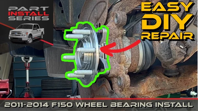
Video loads only when you choose to play.
Match the hub and prepare the job
For a confirmed hub-bearing fault or damaged hub splines. An IWE actuator is a separate part.
Our Ford/Motorcraft option · One front corner
Motorcraft HUB353 hub & bearing assembly
Ford part number CL3Z-1104-M
Catalog option for 2011–2014 F-150s with part-time 4WD and base-payload configuration. Confirm your truck by VIN before ordering.
2WD, 4A, Raptor or another payload package? Check the specific catalog application; this recommendation does not confirm those trucks.
Amazon search results can include other parts. Confirm the Motorcraft part number, seller and VIN fitment before buying.
As an Amazon Associate I earn from qualifying purchases.
Have these ready for one side
- 1 hub assembly — Ford lists the sensor ring and wiring with HUB353.
- 1 new axle nut + 4 new hub bolts — order separately unless confirmed in the box.
- Brake-bracket hardware — for 2013–2014, Ford’s bulletin lists 2 new bolts per side. For 2011–2012, confirm the truck-specific replacement and thread-treatment requirements.Ford’s per-side hardware list →
Hardware numbers and other supplies
For 2013–2014 F-150, Ford’s TSB 18-2273 parts table lists W706890-S439 hub bolts, N802827-S100 halfshaft nut and W714743-S439 brake-caliper bolts. These are parts-counter starting points from the 2018 bulletin; have Ford confirm current numbers and quantities by VIN. They are not a blanket 2011–2014 hardware kit.
- 2011–2012 or a different configuration: have the supplier match the hub and fastening hardware together; do not extend the bulletin’s year coverage.
- Grease: the video lubricates the seal and axle/IWE contact areas. Match the lubricant to the part instructions and keep it off the braking surfaces.
- Dust cap, IWE and axle: inspect their condition. Order replacements only for damage or a diagnosed fault; an IWE is not an automatic bearing-job purchase.
Ready to take it apart?
- Parts matched: confirm year, drivetrain, payload and VIN with Ford; have the hub and required new hardware.
- Specifications ready: resolve the axle-nut specification and brake-fastener requirements before disassembly.
- Tools ready: safe support, caliper hanger, sockets and torque wrenches. Open the tool list below.
Tools and setup
Have secure lifting equipment, a caliper support and torque wrenches covering both the inch-pound harness fastener and the high-torque hub/brake fasteners. The video’s sockets are listed below; replacement nut sizes can differ.
Before lifting the truck, confirm the axle-nut specification and have the new hardware ready.
Allow extra time for a seized hub. The original guide estimates about an hour for removal and installation; that is not a guarantee for a rusted truck.
Tools
Remove the old hub
With the wheels still on the ground loosen each lug nut 1/4-3/4 turn, this will ensure the tire doesn’t spin when trying to crack the lug nuts loose - ↗ 1:25
Safely lift the vehicle off the ground. If using a floor jack, make sure to secure the vehicle with jack stands
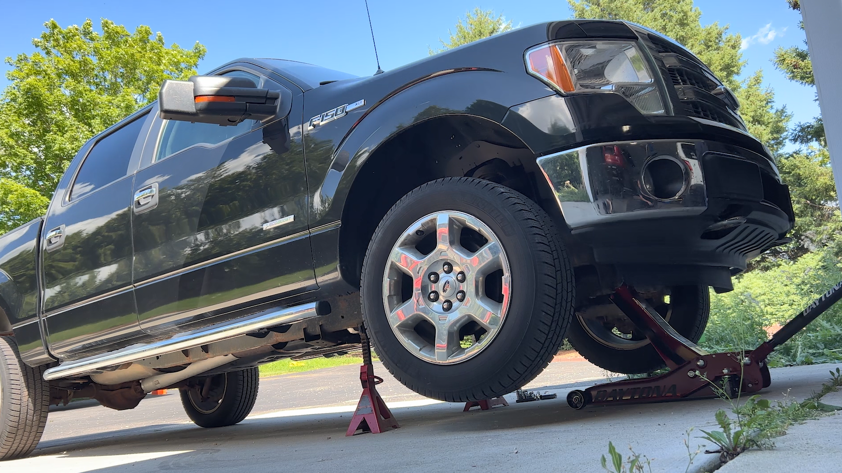 Enlarge: Vehicle supported for front wheel removal
Remove the lug nuts completely and then remove the tire
Using pliers, firmly grasp the axle nut dust cap and rock up and down to remove - ↗ 1:40
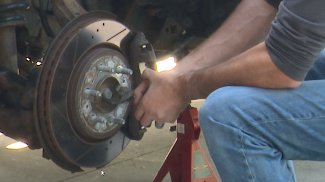 Enlarge: Removing the axle-nut dust cap
With a 15mm socket, remove the axle nut from the axle shaft - ↗ 2:20
Locate and remove the two brake caliper bracket mounting bolts using a 21 mm socket - ↗ 3:54
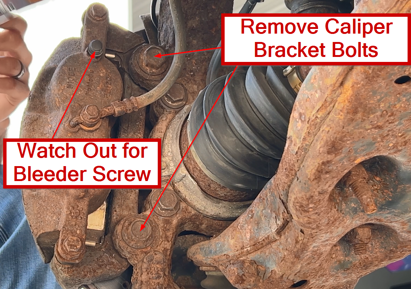 Enlarge: Caliper bracket bolts behind the knuckle
Remove and support the brake caliper assembly, then remove the brake rotor - ↗ 5:05
Locate and remove the 4 wheel bearing hub bolts using an 18mm socket - ↗ 6:04
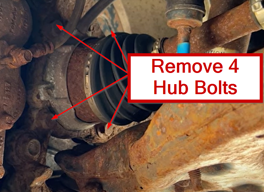 Enlarge: Four hub mounting bolts behind the knuckle
Locate and remove the ABS wiring harness retaining bolt using an 8mm socket - ↗ 6:53
Disconnect the ABS sensor connector and retaining clips - ↗ 7:41
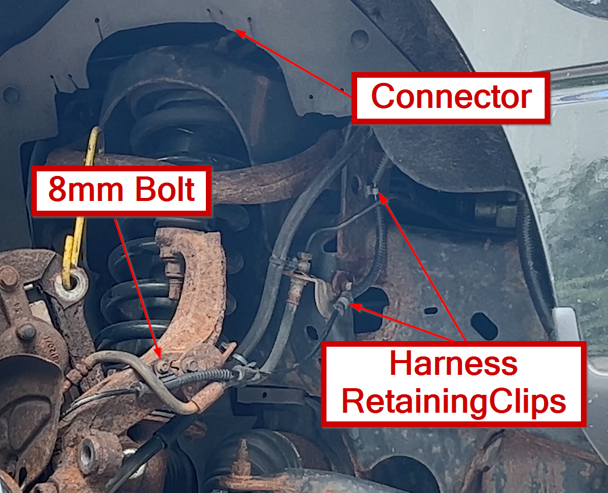 Enlarge: ABS harness connector and retaining clips
Using a hammer, tap on the back of the wheel bearing hub assembly to remove from the vehicle - ↗ 8:41
Install the new hub
The values below follow GoTech’s demonstrated repair. Use the fastener reference and confirm current specifications for your exact truck before tightening.
Inspect the IWE and axle shaft assembly, paying close attention to the gear teeth. If damaged or worn replace IWE and/or axle shaft - ↗ 8:53
Clean the hub mounting surface on the knuckle with emery cloth or a sanding block. Cover the bearing opening with a rag to keep debris out of the IWE; remove the rag before assembly. See the IWE assembly · ↗ 9:05
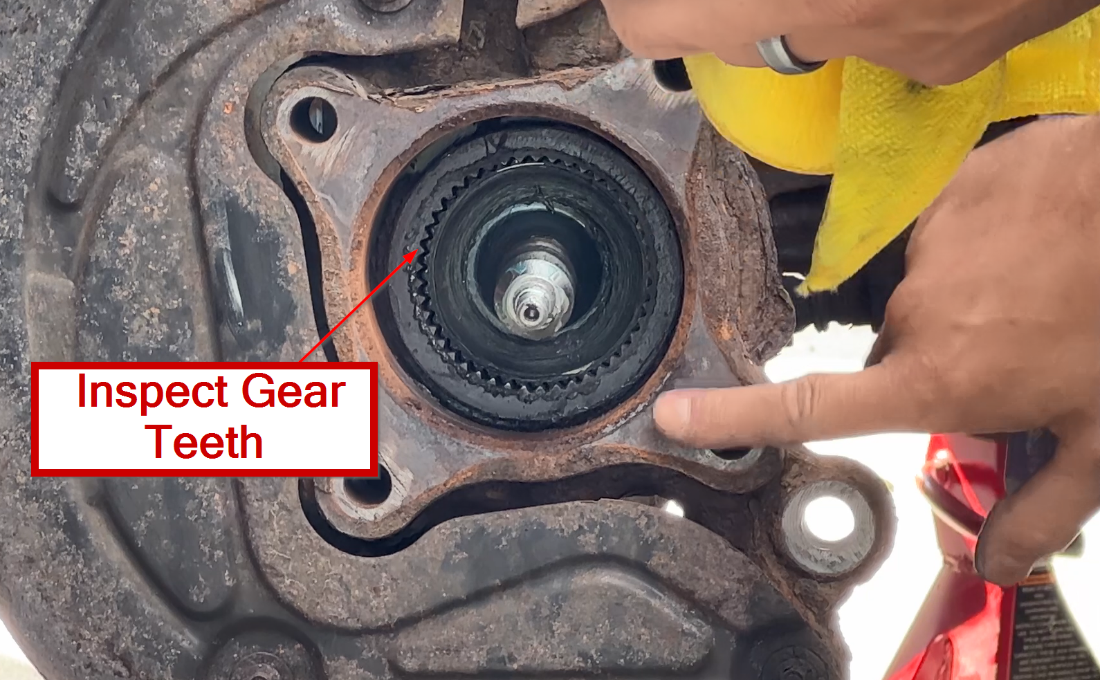 Enlarge: IWE and axle gear teeth inspection
Lubricate the new wheel bearing seal, IWE, and axle with wheel bearing grease - ↗ 9:29
Insert the wheel bearing into the knuckle making sure to verify spline engagement. This can be done by checking the axle shaft protrusion and that the CV axle shaft spins when turning the wheel hub - ↗ 9:40
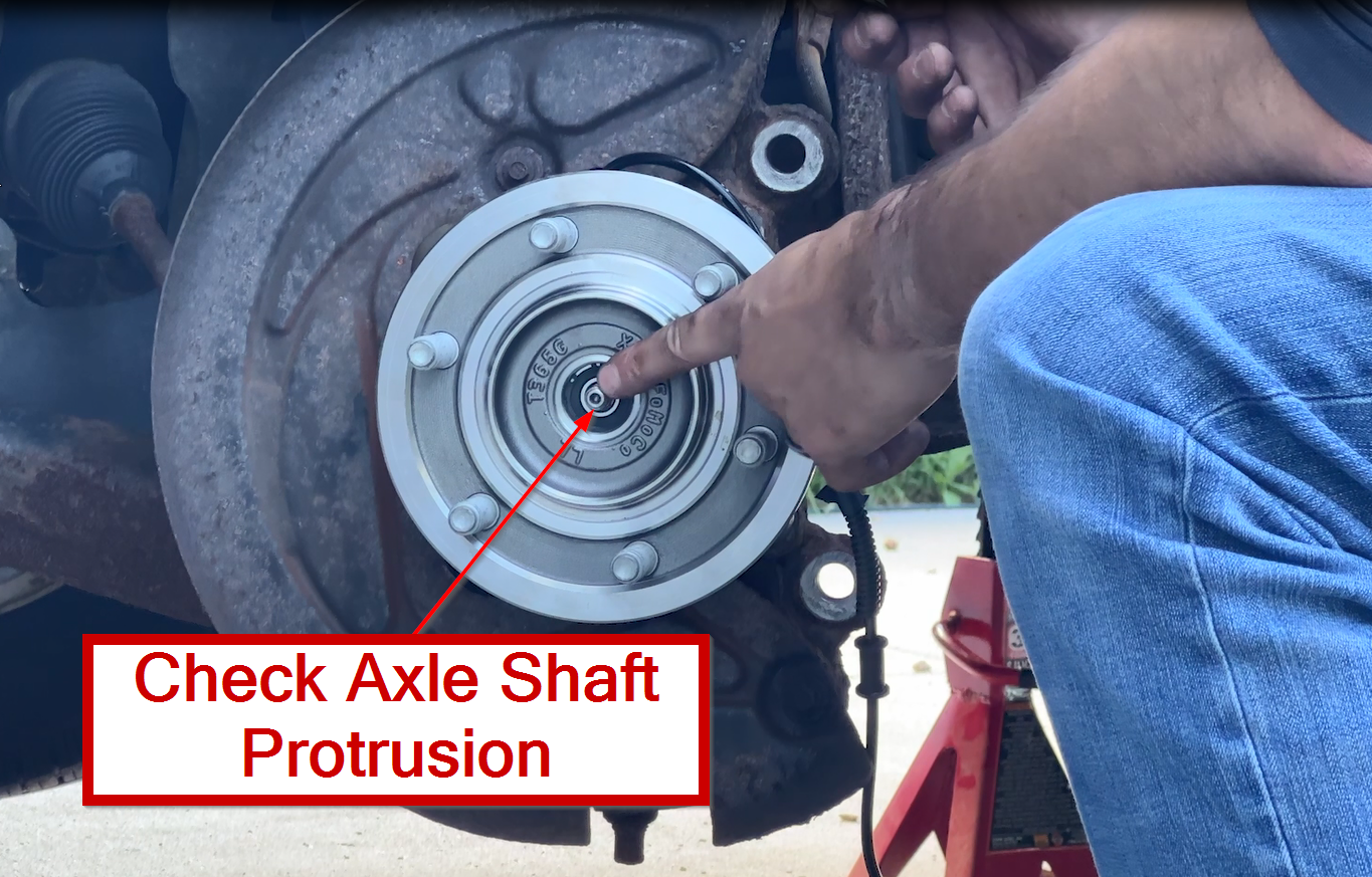 Enlarge: Check axle protrusion and spline engagement
Install and torque the NEW wheel hub bolts to 129 foot pounds - ↗ 10:24
Install a NEW axle nut. GoTech’s demonstration uses 30 foot pounds; confirm the applicable Ford specification before tightening. Then seat the dust cap with light taps. ↗ 12:00Axle-nut specification note →
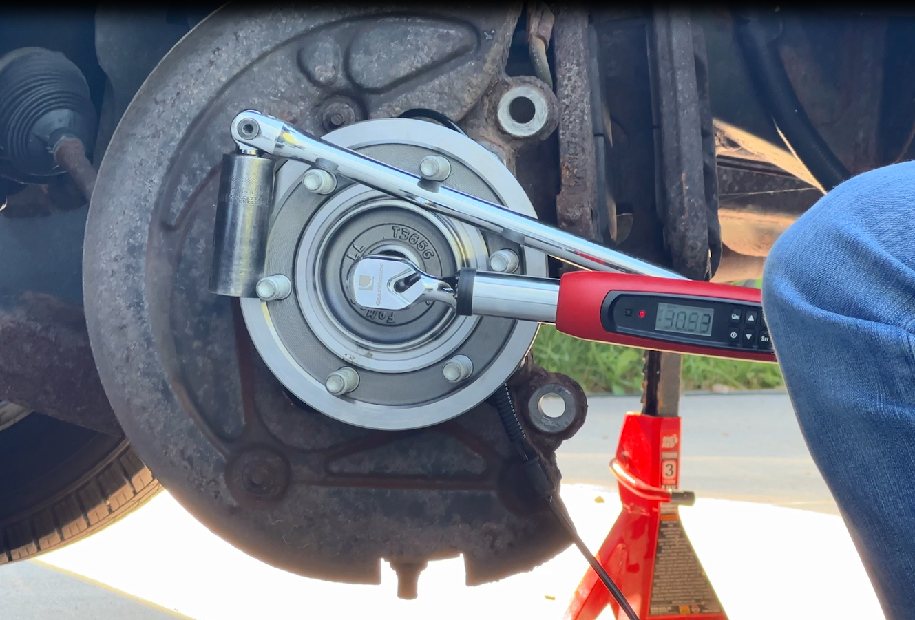 Enlarge: Tightening the new axle nut
Re-route the ABS harness, installing plastic clips and plug in connector - ↗ 13:38
Install ABS harness retaining bolt into knuckle (torque 106 in-lbs.)
Install the brake rotor and caliper/bracket assembly. The GoTech guide specifies 184 ft-lb for the bracket-to-knuckle bolts. The separate 27 ft-lb caliper-to-bracket value applies only if those bolts were removed; this removal sequence leaves the caliper on its bracket. Confirm the truck’s brake fasteners and replacement requirements. ↗ 13:53
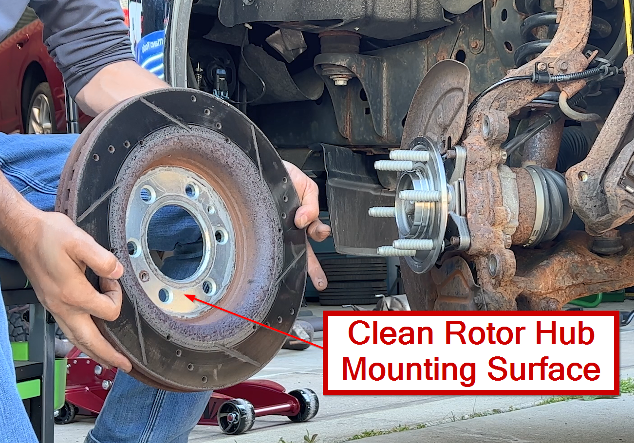 Enlarge: Clean the rotor-to-hub mating surface
Re-install tire and torque lug nuts down to specification in owner’s manual · See the year-specific Ford wheel-nut reference →
Torque reference for the demonstrated repair
These are the values in GoTech’s original guide—not a specification lookup for every F-150. Match the fastener, year and brake/4WD configuration to current Ford service information. Use a torque wrench for final tightening.
Four hub-to-knuckle bolts
129 ft-lb
New bolts · 18 mm socket in the video
Watch hub bolts · 10:24Axle / halfshaft nut
Confirm for your truck
Video: 30 ft-lb, new nut. Published procedure copies differ; check the applicable Ford specification.
Read the specification note →Watch axle nut · 12:00ABS harness retaining bolt
106 in-lb
Inch-pounds, not foot-pounds. Harness bracket bolt, not the sensor mounting screw.
Go to ABS wiring →Caliper bracket to knuckle
184 ft-lb
21 mm socket in the video. Confirm replacement-bolt requirements.
Watch brake reassembly · 13:53Separate caliper bolts — only if removed
Caliper to bracket: 27 ft-lb in the original guide, only if removed. Those are different fasteners from the 184 ft-lb bracket bolts. The demonstrated removal sequence takes the caliper and bracket off together.
Why the axle nut needs a check
GoTech demonstrates 30 ft-lb. Public copies of Ford’s 2011 procedures list 20 ft-lb (27 Nm) for a hub replacement and 30 ft-lb (40 Nm) for IWE installation. We could not establish which specification supersedes the other for every truck covered here. Confirm the current axle-nut specification for your truck and replacement hardware before starting; do not choose by socket size. Procedure sources →
Refit the wheel: Ford manual references
For the factory M14 × 2.0 wheel fasteners in the linked manuals. Clean the mounting faces and dirt/rust from the threads. Match any different wheel or fastener package to its own instructions.
| Manual year | Printed torque |
|---|---|
| 2011 · 2012 · 2013 | 150 ft-lb / 200 Nm |
| 2014 | 148 ft-lb / 200 Nm |
Values are reproduced as printed; the manuals round the imperial units differently. The 2011–2013 manuals specify a wheel-nut recheck within 100 miles (160 km) after wheel removal. Follow your truck’s manual for the tightening pattern and follow-up.
Before calling the repair finished
- Confirm engagement and assembly. Revisit the IWE spline check · 9:40. Do not use the axle nut to pull misaligned parts together. Check the fasteners, dust cap and seated hub.
- Check brakes and wiring. Secure the ABS connector and every routing clip, clear of moving parts. Confirm the brake assembly and wheel are correctly fastened. Restore a firm brake pedal before moving the truck; stop if it does not feel normal.
- Recheck the complaint. When safe to drive, repeat the conditions that produced the noise. Check for ABS/traction warnings, vibration or abnormal 4WD engagement. Record the outcome and the wheel-nut follow-up on the job sheet.
Noise, grinding or a warning light remains
- Hum or growl: return to the bearing-noise diagnosis and compare tires, the other hub and suspension findings.
- IWE ratcheting or grinding: revisit engagement and the truck’s 4WD diagnosis before ordering an actuator. GoTech’s IWE guide shows the separate mechanical job.
- ABS/traction light: check the newly disturbed harness and connector, then diagnose the stored fault. Do not assume another new hub is the answer.
Noise gone and checks normal? Record the result and wheel-nut follow-up. If the original noise, a new vibration or a warning remains, the repair needs another check.
Sources and application limits
The steps, illustrations, timestamps and five restored cautions come from GoTech’s original August 2022 guide and repair demonstration. The torque reference repeats that guide; it is not a newly verified Ford service specification for each model year.
- Ford HUB353 product record: Motorcraft/Ford part identity, part-time 4WD and base-payload scope, sensor ring and wiring. Its “Fits These Vehicles” section lists 2011–2014 F-150 4WD; match the individual truck using Ford’s vehicle selector.
- 1A Auto’s 2011 F-150 demonstration: corroborates 129, 30, 184 and 27 ft-lb values. It uses a different axle-nut socket; socket size is not the torque specification.
- Timken’s general hub installation instructions: caliper support, harness routing, careful installation and torque-wrench use. These are general precautions, not Ford fitment or torque authority.
Public copy of Ford’s 2011 3.5L 4WD hub procedure gives 20 ft-lb (27 Nm) for the new halfshaft nut; the 2011 5.0L 4WD IWE procedure copy gives 30 ft-lb (40 Nm). These are mirrored procedures, not a verified current Ford revision. The difference remains unresolved; no engine-based rule or universal axle torque is inferred.
The year-linked Ford owner manuals above support the wheel-fastener references. Ford TSB 18-2273 supports the labeled 2013–2014 hardware leads; it addresses IWE grinding, not every bearing replacement. The buying checklist, job sheet, shortcuts and completion routes are GoTech editorial additions.
Motorcraft is our catalog-based recommendation; the video does not identify the installed brand. Catalog information checked October 28, 2026. The Amazon link is a part-number search, not a verified listing; no VIN-specific fitment, seller stock or price is confirmed here. Existing tool links may also earn a commission.