
U0101 and no TCM communication: start here
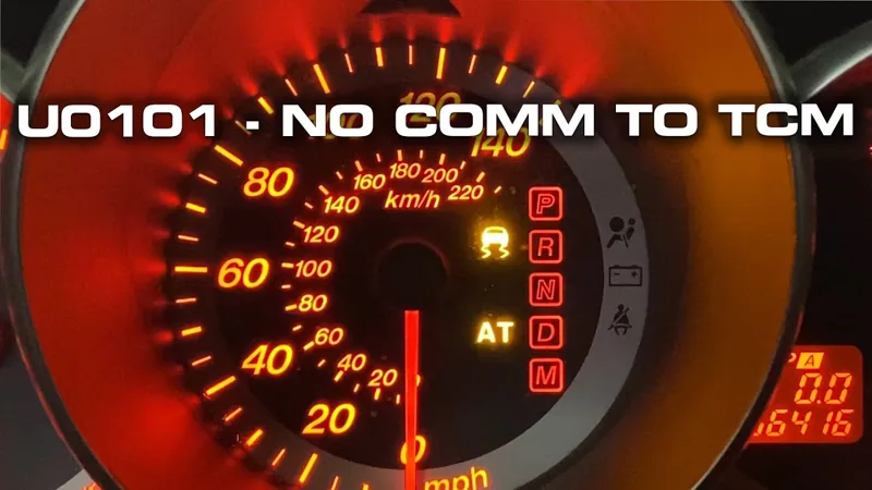
U0101 means lost communication with the transmission control module (TCM). On this Mazda, the vehicle arrives on a flatbed. Engagement is harsh, the shift-position display is missing, and the transmission appears to be in a failsafe gear. The scan tool cannot talk to the TCM.
▶ See the complaint and full scan 0:36- Save the whole scan—not just U0101.
Record which modules respond, which ones report lost communication, and the conditions when it happens. The customer asked to address the transmission first, but the ABS/network faults still belong in the picture.
- Find out what has already been touched.
The owner says a replacement TCM worked for one day. That is useful history, not proof that the new module—or its connector—is good.
- Use the diagram for this vehicle.
Identify the TCM’s network connections and its power and ground circuits. The video starts with CAN signals; the presenter says power and ground still need testing. Their results are not shown.
Is it safe to keep driving?
This car was brought in on a flatbed and was described as far from drivable. If yours has similarly harsh engagement or cannot move normally, arrange transport instead of trying to drive through the fault. The presenter suspects third gear but explicitly says he has no TCM data to confirm it.
Follow the evidence before buying another TCM
| Check | Observed in this Mazda | Next decision |
|---|---|---|
| Module scan | What happenedThe engine computer (PCM) responds. The TCM does not. | What it tells usStart with the TCM’s connections and supplies. PCM communication alone does not certify the entire CAN network. |
| Scope comparison | What happenedSignals are compared at the PCM and TCM. One trace at the TCM looks wrong. | What it tells usCheck what lies between the test points—including the connector contact and the test connection itself. |
| Jumper installed | What happenedThe TCM comes online. The presenter initially blames the wiring he bypassed. | What it tells usThe jumper also moved a terminal. Separate the electrical change from that physical change. |
| Harness checked | What happenedThe splice looks clean; signals look normal along the wire toward the TCM. | What it tells usReconsider the original conclusion before opening more of the harness. |
| Terminal fit | What happenedThe correct-size test lead has noticeably less drag in the suspect network terminal. | What it tells usThe presenter identifies poor mating contact at the TCM connector. Plan the proper terminal/connector repair, then verify it. |
Scope colors here identify channels, not a pinout. The video does not supply a complete probing procedure, verified cavity numbers or a numeric terminal-drag specification.
Why the jumper test fooled him
At about 5:01, he bridges the wiring between the PCM and TCM with a jumper and back-probes. Communication returns. It looks like a clean answer: the wiring in between must be bad.
Then the splice checks out. So does the wire leading back to the connector. The missing piece is what happened when he pushed the back-probe into the connector: it restored contact between the female terminal and the TCM’s male pin.
▶ Watch the jumper result 5:01▶ Hear what the probe actually changed 6:17- WireThe scope can show a normal signal here.
- Mating contactA loose female terminal may not grip the module pin.
- TCM pinThe module still needs a reliable connection.
What changed: inserting the back-probe disturbed the contact. The return of communication did not isolate the bypassed wire as the fault.
Why did the piercing-probe result look normal?
The presenter explains that testing the wire with a piercing probe showed a normal network signal. That measurement did not prove the wire’s terminal was making reliable contact with the TCM pin.
That is the distinction to keep: where did you measure, and what connection did that measurement actually include? This guide does not prescribe piercing insulation or jumping CAN wires. Use the approved access method and circuit information for your vehicle.
▶ Compare wire testing with connector contact 6:46Check terminal fit without creating a new fault
The useful check starts at 7:30. The presenter uses a matching terminal-test lead to compare contact drag. He first picks the wrong size, stops, and changes it. That small correction matters.
▶ Watch the terminal-fit check 7:30- Match the lead to the terminal.
Follow the vehicle’s connector handling and power-down procedure before disconnecting or checking fit. Use the specified terminal-test tool; do not force a larger probe into the cavity.
- Judge the contact, not just the wire.
In the demonstration, some terminals give a slight drag and the suspect contact feels much looser. Use the correct reference or service specification. Different terminal types do not make a valid comparison.
- Keep the test from becoming a temporary fix.
Record whether inserting or moving the test lead changes communication. A connector that only works while held, wedged or propped by a probe has not passed.
Tools that serve a purpose here
- Full-system scan tool: record the module responses and recheck TCM communication.
- Lab scope and suitable leads: compare signals at the documented test points. Matching wire colors alone is not enough.
- Correct terminal-test leads: check the connector’s mating fit. The video uses an AESwave kit; AESwave’s terminal-lead range is a starting point, not confirmation that every lead fits this connector.
- Vehicle-specific service information: identify cavities, test conditions and the approved terminal repair. No replacement part number is established by this case.
The drag comparison is qualitative. It identifies the presenter’s suspected failed contact; it does not provide a factory force specification or authorize squeezing a terminal into shape.
From the terminal fault to a verified repair
The video stops at fault identification. It does not show a terminal replacement, a final all-module scan or a road test. Communication returning during a probe test is not the same as a completed repair.
The following is the repair handoff and verification plan to use with the matched service procedure—not a claim about work completed in the video.
- Repair the confirmed contact fault properly.
Identify the correct terminal, connector and approved repair method. Inspect the mating module pin and the connector’s seating/retention. Use the appropriate tools and sealing instructions; do not leave the jumper or probe installed.
- Test it in its normal assembled state.
Remove test aids, secure the connector and repeat the communication check under the original fault conditions. Complete the power/ground and network checks needed to support the diagnosis.
- Confirm the customer’s complaint is gone.
After saving the original scan and following the prescribed code-clear procedure, recheck TCM access, returning communication codes, the shift-position display and engagement. Only carry out a road test when operation is safe. Address remaining ABS/network faults separately.
If the result does not match this Mazda
- The TCM stays offline and terminal fit is normal
- Continue the vehicle-specific power, ground and network diagnosis. U0101 alone does not identify which component failed.
- Several modules are offline
- Revisit the full scan and shared paths in the wiring diagram. Do not limit the diagnosis to the TCM just because this case ends there.
- It works only with the test lead installed
- The test has changed the fault. Recheck contact fit and test setup before calling the wiring or module good.
- The code returns after repair
- Save the new conditions and scan. Return to the evidence; a temporary recovery is not a verified fix.
DIY owner: what to bring to the shop
You can get useful work done without opening the harness: record the warning lights, when shifting changes, the scan report if you have one, and the details of any TCM replacement. Leave live CAN probing and terminal repair to someone equipped for it if those checks are new to you.
A useful handoff
“The car has U0101 and the scan tool cannot communicate with the TCM. Here is when it happens and what has already been replaced. Please check module communication, power/ground and the TCM connector’s contact fit before recommending another module.”
Use only the symptoms and history that are true of your car. This Mazda’s loose terminal is a case example, not your diagnosis.
Does this apply to every Mazda3 with U0101?
No. The confirmed case is a 2007 Mazda3, 2.3L four-cylinder, automatic. It does not establish identical connectors, terminal parts or network layouts for other engines, years or transmissions. Confirm the actual vehicle and circuit information first.
▶ Hear the vehicle and engine identification 0:14Put this case to work on the next network problem
Watch the original diagnosis
Every timestamp above plays here. Use “Back to where you were” to return to the check you were reading.
Video loads only when you choose to play.
What this guide covers
One filmed 2007 Mazda3 2.3L automatic, not an all-Mazda U0101 repair procedure. The narrator identifies the vehicle at 0:14–0:23. Exact engine code, transmission code, connector cavity numbers, terminal part number and repair specifications are not established here. The video ends with the terminal fault identified; permanent repair and road-test results are not shown.
Written by GoTech from the original video. The linked source moments let you check the explanation against the demonstration.