
P0300 after plugs and coils: where to start
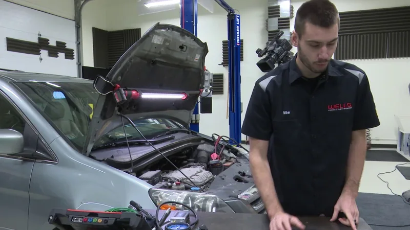
This Odyssey trembles at idle and gets worse as it warms up. Mike reads P0300 along with cylinder-specific misfire codes for cylinders 2, 4 and 5. The owner has already replaced all six plugs and coils. That work did not resolve the complaint.
▶ Read the codes and repair history Part 1 · 1:23- Save the conditions before clearing anything.
Record the codes, freeze-frame data, cold-versus-warm behavior and previous work. A warm-idle problem needs a warm-idle check at the end.
- Look at fuel correction and engine behavior.
Mike reviews fuel trims and checks manifold vacuum. Those findings guide him toward mechanical testing; they do not prove every injector, ignition part or intake seal is good.
- Get evidence before opening the engine.
He suspects valve clearance, then uses a pressure transducer to investigate. The feeler-gauge check in part 2 confirms the tight clearance.
What if my symptoms do not match?
A persistent single-cylinder fault, an injector-circuit code or a clearly different fuel-trim pattern needs its own diagnostic direction. Start with our P0300 overview. The Honda Fit P0303/P0203 case follows an electrical fault, not this Odyssey’s valve repair.
A separate engine-mount fault also appears in the first scan. Its separate diagnosis is not shown. Match a vibration complaint to the engine’s misfire data before assuming they have the same cause.
If the engine is shaking severely, losing power or the check-engine light is flashing, stop the road test and arrange diagnosis. This successful case is not clearance to keep driving with an active misfire.
What pointed to tight exhaust valves?
The useful part is the sequence. No single number below is a shortcut to the repair.
| Check | Observed result | Next decision |
|---|---|---|
| Previous ignition work | In this OdysseyNew plugs and coils; rough idle remains. | Next decisionKeep testing. Replacement history is not an ignition-system pass. |
| Fuel trims / vacuum | In this OdysseyThe displayed long-term corrections are at 1.00. Warm manifold vacuum is about 21 inHg. | Next decisionMike prioritizes a mechanical check. These observations do not exclude every fuel or air fault. |
| Cylinder 4 pressure | In this OdysseyThe pressure trace returns toward exhaust pressure early relative to bottom dead center in his comparison. | Next decisionInspect valve clearance. Use a matched reference and comparable test conditions. |
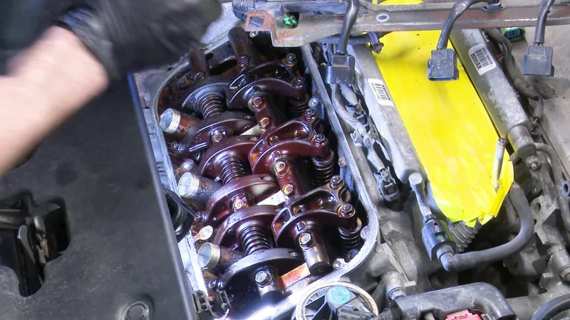
| Direct clearance check | In this OdysseyThe first exhaust clearance measured on cylinder 6 is about 0.007 inch; he reports tight exhaust valves across the engine. | Next decisionAdjust to the vehicle’s confirmed specification, then remeasure and repeat the original tests. |
Technician detail: 1.00 is not 1% fuel trim
The scan tool in part 1 displays fuel correction as a multiplier. Here 1.00 is neutral and 1.14 means about 14% added fuel. Mike sees that positive short-term correction in one bank’s freeze-frame data; calling the whole fuel system “perfect” would overstate the evidence.
Compare the right parameter, bank and operating condition before interpreting the value. The warmed-up vacuum reading is also a case observation, not a universal specification.
Why the pressure trace matters
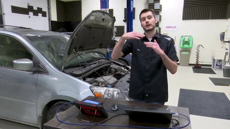
Mike installs a pressure transducer in cylinder 4 and captures it with an ignition reference while the engine runs. The test cylinder is not firing. This shows pressure changes through the cycle; it is not a conventional cranking-compression result.
▶ See the pressure-test setup Part 1 · 10:02His explanation is that less clearance changes when the rocker begins moving the valve. The pressure trace gives him a reason to inspect; the direct measurement gives the adjustment a firmer footing.
Scope detail: keep the comparison honest
- Use a suitable running-pressure transducer, the correct adapter and the prescribed fuel/ignition-disable procedure for the test cylinder. Keep ignition energy safely controlled; do not copy an improvised spark connection.
- Record cylinder, engine temperature, idle speed, transducer setup and reference points. Mike notes temperature differences in his captures.
- Check the engine-specific known-good pattern. The video’s 30–50° rule of thumb is not a Honda pass/fail specification. Mike says the small opening-angle difference alone would not justify teardown.
- His pressure-derived duration estimates are approximate cursor readings, not factory camshaft specifications.
- Absence of a correlation code does not independently prove correct mechanical timing. Check it separately if the evidence calls for it.
Which Odyssey engine is this?
Confirmed: a 2006 Honda Odyssey with a 3.5L V6. Mike identifies it in all three introductions. The series does not establish the exact engine-code suffix or trim.
▶ Hear the vehicle introduction Part 1 · 0:08Honda’s Canadian 2006 specifications show different valvetrain/VCM configurations by trim. Confirm your engine and the matching service procedure before choosing specifications, gaskets or parts. We do not label this as a confirmed J35A6 or J35A7 procedure.
This is a tight-valve case. It does not establish a VCM fault, a VCM-disable repair, or identical valve-adjustment instructions for every Honda 3.5L.
Before taking the covers off
Part 2 starts with a cold engine that sat overnight. This is an involved access job, especially at the rear bank. Use Honda service information for your exact application alongside the demonstration.
Have the job ready before you start
- Correct intake/exhaust feeler gauges; angled blades and an inspection mirror help at the rear bank.
- Suitable adjuster and locknut tools, a torque wrench, and the specified fastening values.
- The cylinder-identification and cam-position procedure, safe engine-rotation instructions and access/support equipment.
- VIN-matched cover seals and any other required replacement gaskets; clean protection for exposed intake openings.
- A scan tool and a way to repeat the original symptom check. Scope verification needs the appropriate equipment and experience.
Can I do this at home?
It is a realistic job for an experienced DIYer who can identify the correct cylinder position, judge feeler-gauge drag, torque the locknut and recheck the clearance. It is not a first repair to learn those skills on. The rear bank has limited visibility, and several access/reassembly steps are condensed in the video.
If you are unsure about a cylinder mark, the measuring contact points or the specification, stop before adjusting it. You can still use the shop brief to get an evidence-led diagnosis.
Valve adjustment: the checks worth slowing down for
The values used in the filmed repair
Intake: 0.008–0.009 inch.
Exhaust: 0.011–0.013 inch.
Mike states these ranges and uses the upper end while checking/adjusting this cold engine. Confirm the current specification and required temperature for your exact engine before using them. The filmed figures are not a fitment lookup.
▶ Hear the stated clearance ranges Part 2 · 8:53- Protect the openings and plan rear-bank access.
Mike covers exposed intake openings and replaces deteriorated cover seals. Keep track of anything used to block an opening, and remove it before reassembly. The harness above the rear cover makes access harder.
▶ Protect the intake openings Part 2 · 3:36▶ Find the rear harness fastener Part 2 · 30:45 - Match the mark to the cylinder you are measuring.
He aligns the cam-sprocket cylinder mark with the inspection reference. The valves must be in the prescribed closed position. At one point he starts checking the adjacent cylinder, notices it is engaged and corrects himself—an easy mistake to catch before turning an adjuster.
▶ Find the cylinder-position reference Part 2 · 6:48▶ Catch the wrong-cylinder check Part 2 · 21:20 - Measure first; distinguish access trouble from tight clearance.
The first measured exhaust valve, on cylinder 6, is about 0.007 inch. Mike does not supply a numeric before measurement for every valve. Rear access makes blade angle and visibility important. He reports that the intake valves were within range; that does not justify skipping their measurements on another engine.
▶ Compare intake and exhaust clearance Part 2 · 11:50 - Hold the adjuster, tighten to specification, then measure again.
A blade should have the specified feel without being trapped or freely loose. Mike has to readjust his first setting after tightening. Do not copy the number of turns he happens to use; the final clearance is what matters.
▶ Watch adjustment and the recheck Part 2 · 15:19 - Finish both banks and account for every valve.
Use the correct cylinder sequence and service procedure. Check the clearance again after tightening, then complete the specified sealing, torque and reassembly checks.
▶ Move from the front to the rear bank Part 2 · 27:20▶ Hear the final clearance findings Part 2 · 38:19
What do I still need from service information?
The exact engine identification, temperature limit, cylinder-position/rotation procedure, adjuster-locknut torque, cover and intake fastening sequence, sealant locations, replacement seals and complete access/reassembly instructions. We do not invent these from a fast-forwarded video.
Mike also undertakes timing-belt and water-pump work. That work needs its own procedure; it is not a required addition to every valve-adjustment job.
What changed after the repair?
Nearly two weeks and 500-plus miles later, Mike reports no check-engine light, no further rough-idle complaint and no recurring misfire complaint. He shows no stored DTCs, then repeats the cylinder 4 pressure capture.
▶ Check the road follow-up and stored codes Part 3 · 1:12Rough warm idle
Misfire codes remain after plugs and coils. The pressure comparison points toward an early exhaust event. Direct inspection finds tight exhaust clearance.
Complaint resolved in the follow-up
The repeated trace crosses bottom dead center while pressure is still rising toward equalization, unlike the earlier capture. The original symptom and code findings have also improved.
Keep the full repair history attached. Mike also completed the timing belt and water pump before this follow-up. This is a documented outcome after that combined work, not a controlled valve-adjustment-only experiment. No longer-term follow-up or complete monitor-readiness report is supplied.
Your return-to-service check
- Verify all disturbed connections, intake openings, seals and fasteners before running; check for leaks or abnormal noise after reassembly.
- Recheck warm idle and the operating conditions that produced the complaint. Review current/pending codes and misfire data where supported.
- If the pressure test was used, repeat it with a comparable setup and keep both captures.
- Complete the vehicle’s required road/monitor checks. An empty code screen immediately after clearing is not enough.
What if the misfire stays?
Do not keep opening the clearance beyond the specification. Recheck the adjustment and disturbed connections, then return to the remaining evidence: ignition, fueling, air leaks, compression/leakage or timing as appropriate. An adjustment cannot repair a burned valve or every other source of low cylinder contribution.
A useful conversation with the shop
“The van is roughest at ___, and the codes are ___. Plugs/coils were replaced on ___; the symptom changed by ___. Please establish the cause before replacing more parts. If valve adjustment is recommended, show me the clearance findings and explain how you will verify the original complaint afterward.”
Bring your saved codes, symptoms and repair receipts. Ask which other work is being recommended and why. The timing-belt/water-pump work in this video should not silently become part of a misfire estimate.
Need a different starting point? Understand P0300 and the diagnostic branches, or see the Honda Fit injector-circuit case for a different route from misfire to repair.
Watch the three original episodes
Every timestamp above plays here. Use “Back to where you were” to return to the check you were reading.
Video loads only when you choose to play.
Video loads only when you choose to play.
Video loads only when you choose to play.
What this guide covers
This guide follows one 2006 Odyssey 3.5L V6. The spoken introductions confirm the model, year and displacement; the exact engine-code suffix and trim are not confirmed. It is not an all-Honda application list or a substitute for the matched Honda service procedure. Clearance figures in this guide are those stated and used in the video, not independently verified current service specifications. Complete fastening, sealing and access instructions must come from vehicle-specific service information. The later outcome follows valve adjustment plus timing-belt and water-pump work.
Written by GoTech from the original videos. The linked source moments let you check the explanation against the demonstration.