
What the Escape test actually proved
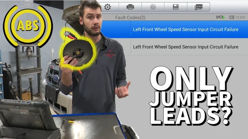
GoTech clears C1155 and it returns immediately at key-on. That gives us a fault we can investigate in the bay. The next move is to feed the left-front circuit with the working right-front sensor and see what changes.
| Test state | What happened | What it tells you |
|---|---|---|
| Original connections | C1155 returns immediately after clearing. | The fault is present now. Save the original codes before changing connections. |
| Right sensor → left input | C1155 is absent. C1145 remains on the intentionally disconnected right-front circuit. | The left-front input accepts the substitute sensor in this test. The new right-front code is explained by the setup. |
| Polarity reversed | Codes appear for both front circuits. | An incorrectly connected test is not evidence of two failed sensors. Verify the specified connections. |
| Wheel rotated by hand | The left-front scan value responds to the borrowed right-front sensor. | The tested left-front signal path can report speed. This does not clear it under every load or intermittent condition. |
Where the case lands: attention returns to the original left-front sensor side. GoTech reports no obvious crack or gap in the exposed tone ring. Sensor replacement and a final repair check are not shown.
▶ The code returns at key-on Escape · 1:34▶ Compare the codes after substitution Escape · 4:25Before you unplug anything
What you need for this kind of test
- An ABS-capable scan tool that reads wheel-speed data. An engine-code reader alone is not enough.
- The correct vehicle wiring information, sensor type and terminal identification. Confirm compatibility before substituting a sensor; two wires alone do not establish it.
- Suitable terminal adapters that will not spread or damage connector terminals.
- A safely supported vehicle, secured against movement, following its lifting and service procedures. The demonstrated test is stationary, with the engine off and wheels turned by hand.
DIY starting point: record the exact ABS codes, when the warning appears and any recent hub, axle or wiring work. If you cannot identify the sensor type and connector sides confidently, use this guide to understand the shop’s test rather than improvise a jumper connection.
The scan tool follows the input
This is the part worth slowing down for. GoTech borrows the right-front sensor, but connects it to the left-front vehicle harness. The scan tool still calls that input “left front.”
Normal connection
- Left-front sensorAt the left wheel
- Left-front harnessVehicle side
- ABS left-front inputShown as LF speed
Demonstrated stationary test
- Right-front sensorBorrowed signal source
- Left-front harnessTemporary test connection
- ABS left-front inputStill shown as LF speed
Original left-front sensor: disconnected from the tested circuit.
Right-front vehicle harness: disconnected; this explains C1145 during the test.
The moving left-front value is now evidence from the borrowed sensor. It is not proof that the original left-front sensor started working.
▶ Identify the sensor side Escape · 1:55▶ Identify the vehicle-harness side Escape · 2:31▶ See the left-front scan value respond Escape · 6:28No pin numbers, wire colors or universal jumper arrangement are supplied here. Use the vehicle-specific circuit procedure. The video demonstrates a polarity-sensitive sensor; guessing polarity is not a substitute for identifying its terminals.
No signal after testing? Check what the test changed
Separate case · 2009 Buick Enclave · Left rear
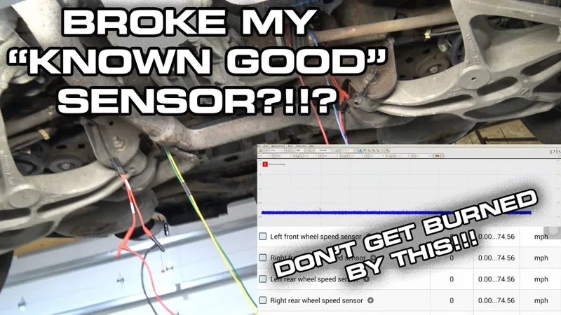
In the follow-up, a working right-rear sensor is connected to the left-rear circuit—and nothing happens. Swapping the other way also gives no speed. It looks like a wiring problem, but the test has changed the module’s operating state.
- Clearing the codes did not restore the signal.
GoTech reports that the module detected the open circuit and shut the channel down. A quick key cycle did not recover it either.
- Letting the ABS module power down changed the result.
In this Buick, GoTech switches the key off and waits until the scan tool loses ABS communication. After key-on, the signal returns and the left-rear circuit responds to the right-rear sensor.
- Recheck the setup before condemning the circuit.
Confirm the sensor connection, polarity and the vehicle’s prescribed reset or wake-up conditions. If the valid test still fails, continue the specified supply, signal and harness checks; do not jump straight to an ABS module.
Sensor, connector or tone ring: earn the repair decision
The Escape has an exposed toothed ring. GoTech looks for splits or gaps and reports none visible. That is a useful inspection, but it is not a measurement of ring runout, sensor clearance or signal quality through a complete driving condition.
- The substitute works; the original does not
- Focus on what changed: the original sensor and its local connection. Check terminal condition and the sensor-to-ring relationship using the correct service information before ordering a part.
- The substitute also fails
- First validate the test setup and module state. Then follow the vehicle’s circuit checks. A missing scan value alone cannot separate the harness from the module.
- The complaint happens only while moving
- This stationary success is not the finish line. Capture wheel-speed behavior under the original fault conditions using an appropriate, safe diagnostic procedure.
Buying parts? Confirm the exact vehicle and sensor or hub arrangement first. The Escape’s exposed ring and the Buick’s bearing-related case do not establish interchangeable parts or a common repair procedure.
Before calling it fixed
Neither video ends with a verified finished repair. These are the checks still needed after the actual fault is corrected:
- Put the system back in its normal configuration.
Remove all temporary leads. Reconnect each sensor to its own circuit, secure the harness and check the connectors.
- Recheck the original fault and the test-created codes.
Keep the original scan record, then clear and recheck as directed by the vehicle procedure. Confirm C1155 does not immediately return and the disconnected-circuit code is resolved.
- Confirm the signals under the conditions that matter.
Check the applicable wheel-speed data and repeat the original fault conditions only after the vehicle is safe to test. Any driving check needs the normal wiring restored and a safe data-recording method—never a driver watching the scanner.
Taking it to a shop?
Ask: Which wheel/input has the fault? Did a compatible working sensor make that input respond? What check after the repair will show the original problem is gone?
Bring your original codes and symptom history. “The light went out” alone does not describe what was tested.
Common ABS testing questions
What does C1155 mean on this Ford Escape?
In the 2011 Escape case, GoTech identifies C1155 as a left-front wheel-speed sensor input-circuit failure. It names the circuit under investigation; it does not identify a replacement part by itself.
Why did C1145 appear after the sensor substitution?
The right-front vehicle circuit was deliberately left disconnected while its sensor fed the left-front input. That explains the right-front circuit code during this particular setup.
Can I test every two-wire ABS sensor the same way?
No. Identify the sensor technology and use the vehicle’s test information. Connector count alone does not establish compatibility, polarity, voltage or an appropriate resistance test.
Does a moving wheel-speed value prove the repair is complete?
It proves that the tested input reported a signal under those conditions. In the Escape demonstration it came from a borrowed sensor. The original fault still needs correction and a check with normal connections restored.
Watch the case and the testing follow-up
Every timestamp above plays here. Use “Back to where you were” to return to the check you were reading.
Video loads only when you choose to play.
Video loads only when you choose to play.
What this guide covers
The primary case is a 2011 Ford Escape with a left-front C1155 fault. Its exact engine, drivetrain, connector pinout and replacement-part fitment are not established here. The separate 2009 Buick Enclave example explains a test-state trap; its reset behavior is not a Ford specification. Neither video shows a completed repair followed by final road-test verification. This is a diagnostic case guide, not a sensor or wheel-bearing replacement procedure.
Written by GoTech from the original videos. The linked source moments let you check the explanation against the demonstration.