
P2135: start with the code, not the parts
The presenter describes a familiar complaint: reduced power, poor acceleration, and a vehicle that may drive normally again after a key cycle. That restart hasn’t established a repair. The fault can return.
You’re diagnosing it
Save the codes and the conditions when power dropped. Is P2135 current or stored in history? Check the application below before following this repair. Other codes or an unmatched throttle body need their own diagnostic path.
You’ve confirmed this repair applies
Start with the correct sensor-cover kit, replacement throttle-body gasket and service instructions. Have a way to check the two throttle-position signals afterward; fitting the cover is only part of the job.
- Throttle plate moves
- Two sensors report position
- Controller checks their relationship
- P2135 if correlation is wrong
“Agree” means the expected relationship is satisfied. It does not mean both raw voltage readings must be identical.
P2135 alone does not prove that the accelerator pedal, wiring or entire throttle body needs replacement. This video takes us through the sensor-cover repair selected for this Equinox; it does not demonstrate a complete circuit-by-circuit diagnosis.
▶ Hear the reduced-power complaint 1:58Does this sensor-cover repair apply to your GM?
Our demonstrated vehicle is a 2007 Chevrolet Equinox with a 3.4L engine. The presenter identifies it directly, then works through bulletin 12-06-04-003A. Don’t stretch that into a procedure for every Equinox or every GM throttle body.
▶ Confirm the Equinox and engine 0:41Check the bulletin’s listed applications
GM’s March 2014 bulletin lists:
- Buick Lucerne: 2009–2011
- Chevrolet Malibu: 2006–2008; Uplander: 2006–2009; Impala: 2006–2011; Equinox: 2007–2009
- Pontiac G6 and Montana SV6: 2006–2009; Torrent: 2007–2009
- Saturn Vue: 2006–2009; Relay: 2007; Aura: 2007–2009
It also requires an applicable engine RPO: LGD, LZ4, LZ8, LZE, LZ9, LNJ or LZG. Model/year alone is insufficient.
The historical cover part number is 19300180. That is a reference, not a current fitment or availability guarantee.
Before ordering, match your VIN, engine RPO and existing throttle body to current parts and service information. Confirm what comes with the kit, including the cover seal and new retaining clips; the mounting gasket is a separate item to account for.
DIY: decide this before taking it apart
You’ll be handling small gears, tight clips and an electronic throttle. You need a clean work area, the correct hand tools and a scan tool that can display the required throttle data — a basic code reader may not do that.
If you can’t verify fitment or complete the scan check and learn, a useful shop request is: “Please confirm whether the sensor-cover repair applies to my P2135, and include the agreement check and relearn.”
Remove and clean the throttle body
On this Equinox, the air inlet and connectors come out of the way first. The throttle-body and mass-airflow connectors have locking tabs. Release those before pulling on the connector.
- Work with the ignition off.
Keep hands clear of an energized throttle. Support the removed assembly on a soft, clean work surface; don’t clamp it in a vise or drop it. Wear eye protection for the clips and cleaning work.
- Notice what is actually blocking removal.
In the filmed 3.4L installation, a coolant pipe prevents the body sliding off its two studs. The presenter removes the studs with an external Torx socket, then lifts the throttle body out without opening the cooling system. Check your layout before trying that shortcut.
- Inspect both sides of the bore.
The inlet looks fairly clean, but there is much more buildup on the manifold side. Inspect for damage, clean the bore and plate with a suitable product on a towel, and account for the old mounting gasket. Don’t immerse the assembly.
Fit the sensor cover without forcing it
This is the part to slow down for. The cover, sensor drive and gears have to line up before the clips hold everything together.
- Keep the cover and gear under control.
The rubber band holds the cover while the old clips come off. Lift the cover with the sensor side facing upward and keep the intermediate gear in place. Don’t pry against the machined sealing surface. Follow the service procedure if anything drops or is damaged.
- Account for what came off.
Inspect the old cover’s gasket and the two female motor terminals. The video checks that they stayed with the old cover. Inspect the plastic gear for damaged teeth before continuing.
- Line up the new sensor before seating the cover.
The presenter adjusts the sensor’s drive-slot position to the service illustration, checks all three alignment tabs and makes sure the gear is seated. He holds the plate at the illustrated wide-open position for assembly. Use that illustration — “about halfway” in the video is not a measurement to guess from text.
- Seat the cover, then install the new clips in order.
The cover should sit evenly against the housing. The first clip fights him; he stops, reopens the assembly and checks alignment before trying again. A stubborn clip is a reason to recheck the fit, not to use the clip to pull a crooked cover into place.
Use the GM alignment and clip illustrations, pages 4–5 alongside the video. We haven’t substituted a guessed diagram for those positions.
Verify the signals, then complete the throttle learn
Don’t call it fixed just because the new cover is on. At 20:28, the presenter describes reinstalling the assembly and checking the TP Sensor 1 and 2 Agree/Disagree parameter through throttle movement. That scan result is explained, not shown.
Signal agreement
The scan check asks whether the two position signals agree through the required sweep. An idle that sounds normal can’t answer that question.
Throttle / idle learn
The learn lets the controller adapt after this work. It comes after the assembly and signal checks; it doesn’t repair a sensor that still reports incorrectly.
What about the video’s “no scan tool” advice?
The presenter describes a three-minute idle, a one-minute key-off and another three-minute idle, then discusses driving if idle has not learned. Later he says a DIYer may not need a scan tool.
Keep those two jobs separate. Monitoring idle is not the same as checking sensor agreement. The guide does not replace the required scan check with a timed idle routine, or present that routine as universal. Use the current throttle/idle learn procedure for the exact vehicle, including prerequisites and any scan-tool requirements.
GM’s bulletin specifies ignition-on scan verification and directs throttle-body replacement if agreement fails after this repair. It then refers to vehicle-specific service information for Throttle Learn Reset.
Before handing the vehicle back
- Finish assembly, connector locks, intake connections and vehicle-specific tightening requirements.
- Record the actual sensor-agreement result and complete the specified learn.
- Recheck codes, idle and throttle response. Investigate any returning fault.
- Confirm the original complaint is resolved under appropriate, safe conditions. Don’t road-test a vehicle with unreliable acceleration in traffic.
This is the finish-line checklist, not a claimed result from the video. No completed final scan, relearn or road test is shown.
Questions before you buy a part
Does P2135 mean I need a complete throttle body?
Not automatically. This video demonstrates a replaceable sensor cover on the identified Equinox. Confirm the application and the prescribed checks before choosing a cover or a complete assembly.
Can cleaning alone fix this P2135?
The source demonstrates cleaning and sensor-cover replacement together. It does not establish cleaning alone as the repair for the correlation fault.
Can I use this on a 2.4L Equinox or a Silverado?
The filmed engine is a 3.4L. This page does not establish the repair for a 2.4L Equinox or a Silverado. Match your vehicle and throttle body to its own service information rather than transferring the procedure by code alone.
Did the video prove the repair worked?
It shows the sensor-cover replacement and explains the final checks. It does not show a completed scan result, learned idle or road test. Those remain checks to complete on your vehicle.
Keep the next check connected
Watch the original diagnosis and repair
Every timestamp above plays here. Use “Back to where you were” to return to the check you were reading.
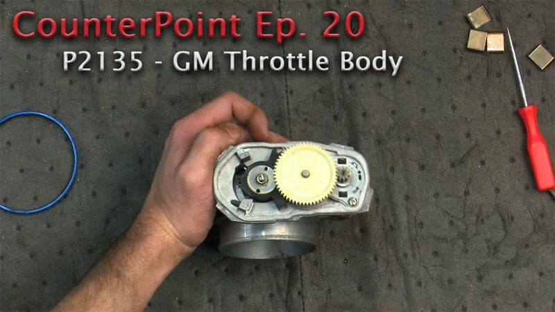
Video loads only when you choose to play.
What this guide covers
The vehicle and 3.4L engine are named at 0:44 in the original video. This is a repair demonstration, not a complete electrical diagnosis for every P2135. The video does not show the final scan-tool results, completed relearn or road test. Use current vehicle-specific service information for fitment, wiring, tightening specifications and the full learn procedure. No VIN, engine RPO or replacement-kit number is established for the filmed vehicle.
Written by GoTech from the original video. The linked source moments let you check the explanation against the demonstration.