
Compare the reading with a real pressure change
The fuel tank pressure (FTP) sensor reports EVAP vapor pressure or vacuum. This is different from fuel-rail pressure. A fixed reading can point to the sensor, its circuit or a test that never changed the pressure.
Record the baseline
Save the codes, PID name, units and test state. Establish the vented or atmospheric condition specified for the vehicle, then compare with its expected reading. Pressure and sensor voltage have different baselines.
Check the response
Use the vehicle’s approved EVAP test to create and release a controlled pressure or vacuum change. Confirm that the physical change occurred, then check whether the reading follows it repeatably in the expected direction. Do not apply unrestricted shop air or use a generic pressure setting.
If the reading disagrees, check the circuit
With the correct connector diagram and back-probing method, compare the sensor’s signal with scan data. Check the reference supply and low-reference circuit against the vehicle’s specifications before condemning the sensor. See the multimeter checks.
Watch the 2005 Sierra 5.3L case · 5:00. The presenter checks a fixed reading against the reported pressure response, then investigates the circuit.
Choose the next check from the result
- Scan data and signal both stay fixed: confirm the pressure change and sensor connection, then evaluate supply, ground and signal. Two agreeing readings do not rule out a failed sensor.
- The signal changes but scan data does not: verify the selected PID, its units and the signal path before buying a sensor.
- The sensor responds, but tank vacuum will not release: check purge-valve sealing and the vent path. A responsive sensor may be reporting a real system fault.
- Baseline and response pass, with a leak fault remaining: continue to a controlled EVAP leak test.
After repair, repeat the original baseline and response checks. Restore connections and follow the vehicle’s monitor procedure; a responsive sensor alone does not establish emissions readiness.
What should a fuel tank pressure sensor read?
Start with the PID’s units and reference. Gauge pressure uses atmospheric pressure as zero; a negative gauge-pressure reading means vacuum. That does not mean the sensor should output zero volts.
The voltage baseline and direction of change depend on the application. Ford’s 2020–2023 gasoline OBD summary contains an application-scoped transfer table on printed pages 11–12; it is not a specification for the Sierra case or every Ford.
Convert pressure units when needed, then compare with the correct vehicle specification. A converted value is not a pass/fail limit.
See how the demonstration supports these checks
Read the signal in context
The training source describes the fuel-tank pressure sensor as feedback for pressure and vacuum changes over time. A value matters alongside the system state and whether it changes as expected. This explanation does not provide a vehicle-specific voltage, pinout or pass/fail limit.
A fixed reading is a clue, not a verdict
In the Sierra case, the pressure reading stayed fixed even when the technician reported a release of vacuum. He then compared scan-tool data with a direct signal measurement. A cap-release observation by itself did not isolate a failed sensor.
| Evidence question | Useful distinction | Still needed |
|---|---|---|
| Does the reading match the reported physical response? | Pressure behavior and pressure feedback can disagree. | System state and a reproducible observation. |
| Does the measured signal agree with scan-tool data? | Agreement adds evidence beyond the display. | Application-specific circuit evaluation before a component verdict. |
| What would confirm a repair? | Revisit the original pressure-response mismatch. | A functional recheck; emissions-monitor completion is a separate outcome. |
Multimeter setup and connector precautions
Using a multimeter at the FTP connector
Use the wiring diagram for this vehicle to identify signal, reference supply and low reference. Follow its back-probing method and powered-test conditions. Compare signal voltage with the matching scan PID, then check supply and ground to specification. Do not force probes into terminals or jumper an unidentified circuit.
Watch the source in context
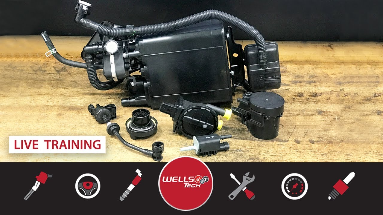
Video loads only when you choose to play.
Did this help you move forward?
Optional. No written response is collected.
About older links to this guide
This guide has been rewritten around the available source evidence. An older section link may land here; use “In this guide” above to find the revised explanation. Original source files are retained in GoTech’s review history.
Sources and vehicle-specific limits
GoTech editorial guidance with AI assistance, based on the original demonstrations and public references below. The test sequence and result routing are our synthesis. Vehicle information supplies connector details, control methods and pass/fail limits; these pages do not claim independent testing on every application.
- Wells CounterPoint, 2005 Sierra 5.3L P0446 · 5:00–12:00: compare the physical response, signal and scan data. Inconsistent numeric automatic captions are not used as specifications.
- GoTech EVAP training · 10:30: pressure feedback in the system.
- Ford 2020–2023 gasoline OBD summary, printed pages 11–12: scoped pressure/voltage transfer table. Confirm applicability before using it.