
Timing marks at a glance
Three different stages of the 2010 Fusion 3.5L demonstration. Keep each diagram with its stage and use the full sequence when doing the work.
Before removal
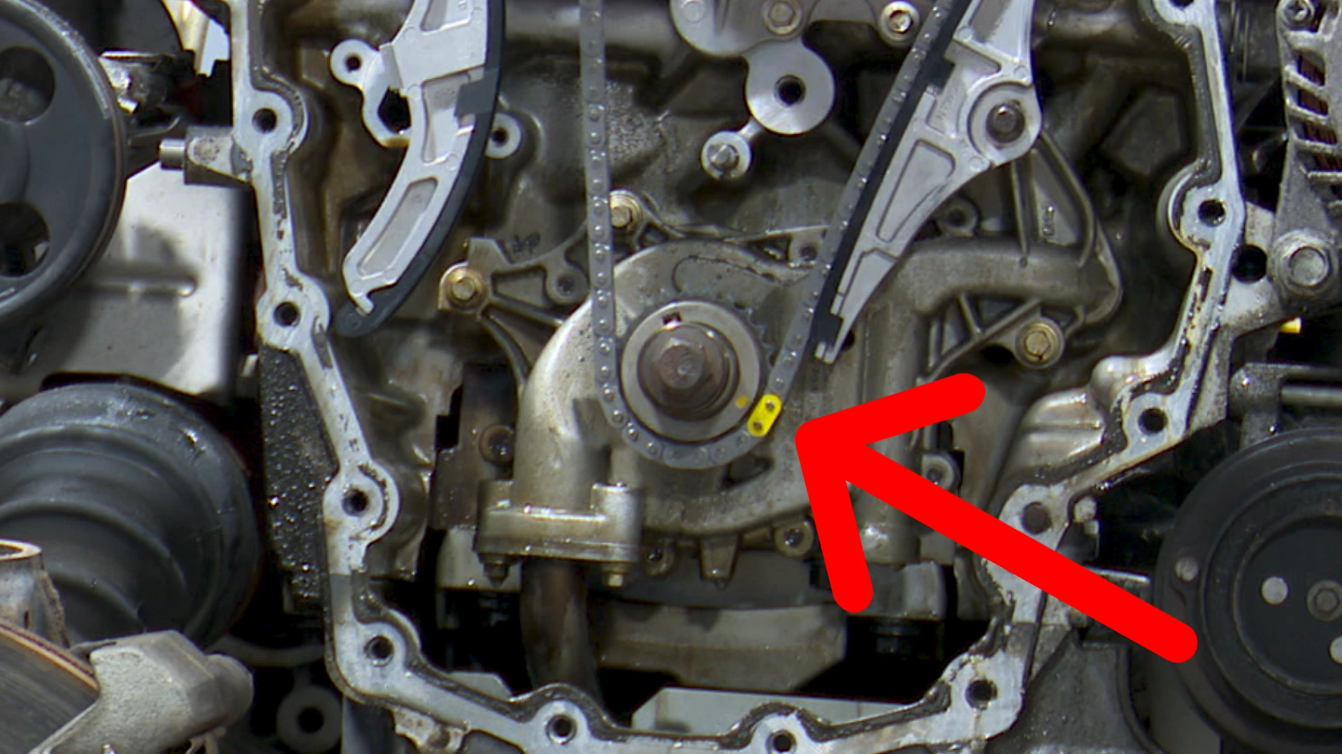
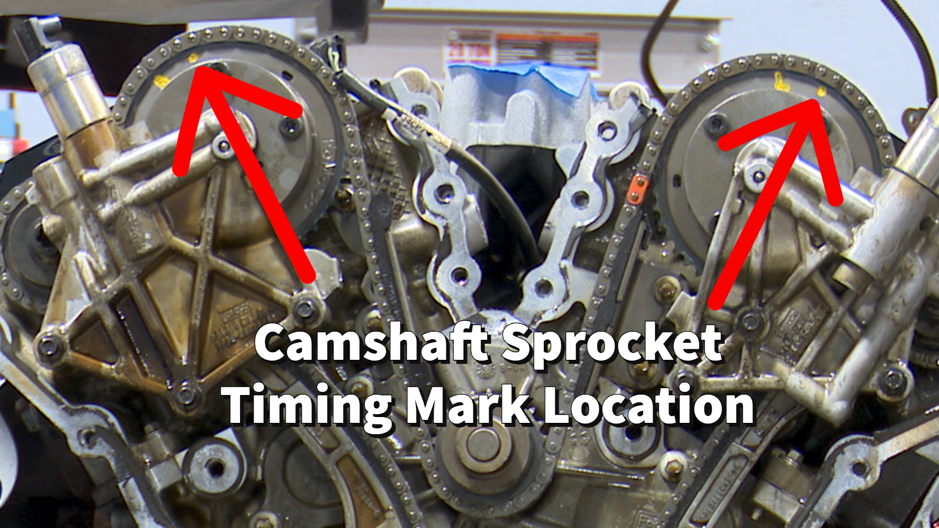
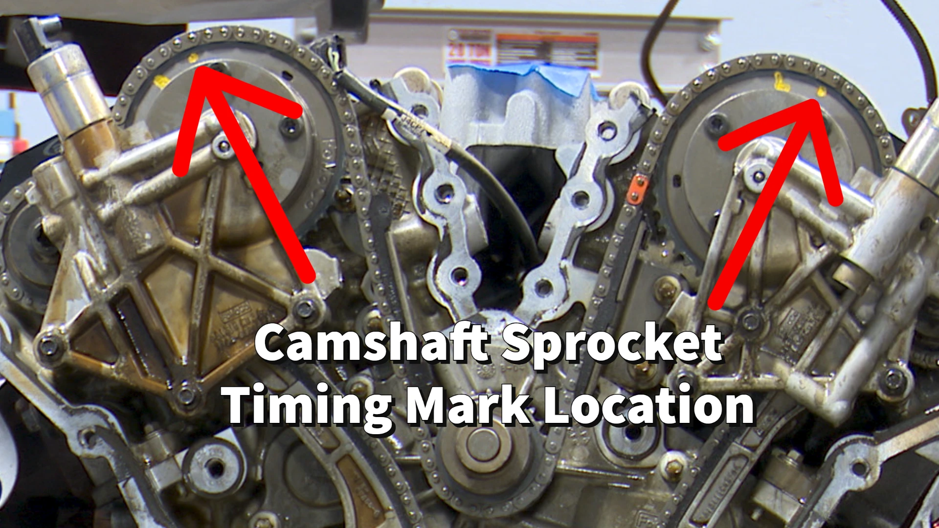
Use the crankshaft and camshaft positions in the removal steps. The colored links are not expected to line up at this stage.

Watch this stage ▶ 2:25Full removal sequence ↓
During installation
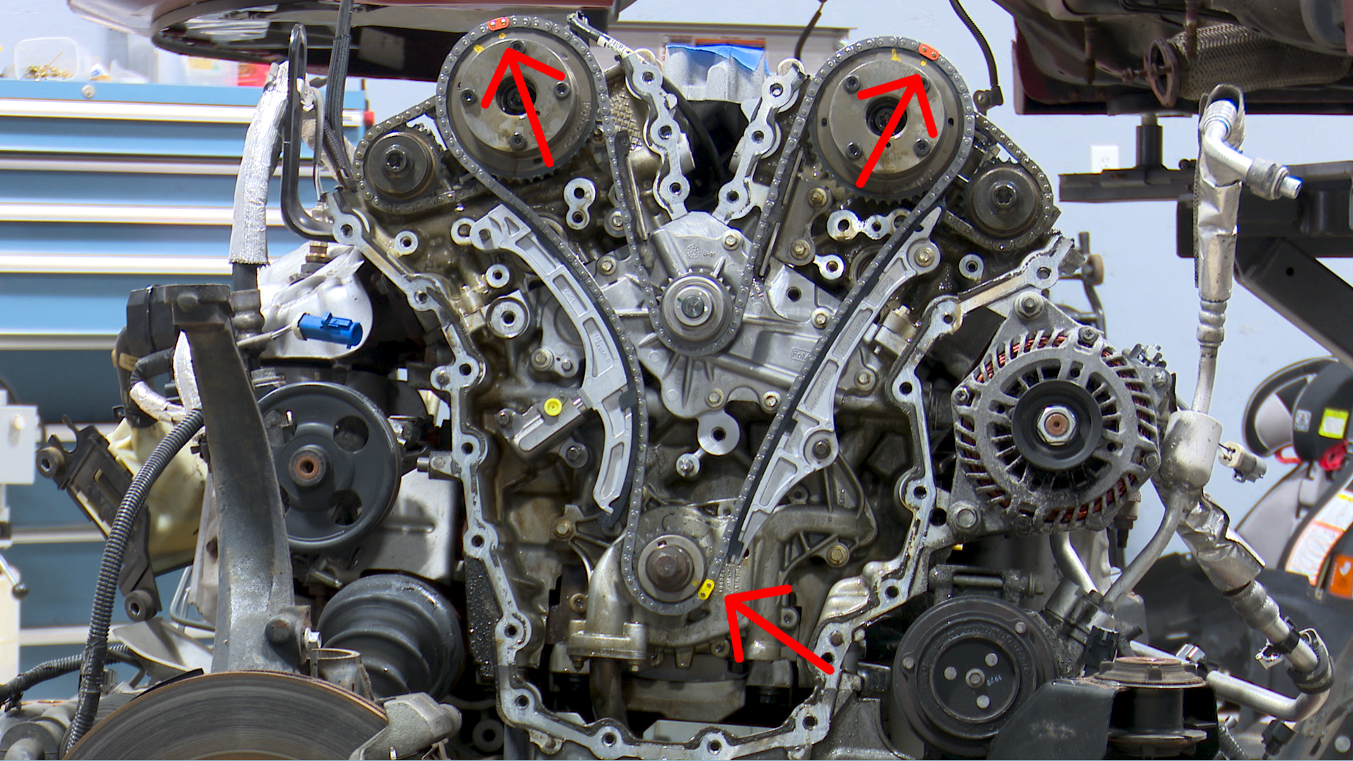
The two matching colored links meet the camshaft marks; the different colored link meets the crankshaft mark. This overview shows all three locations.
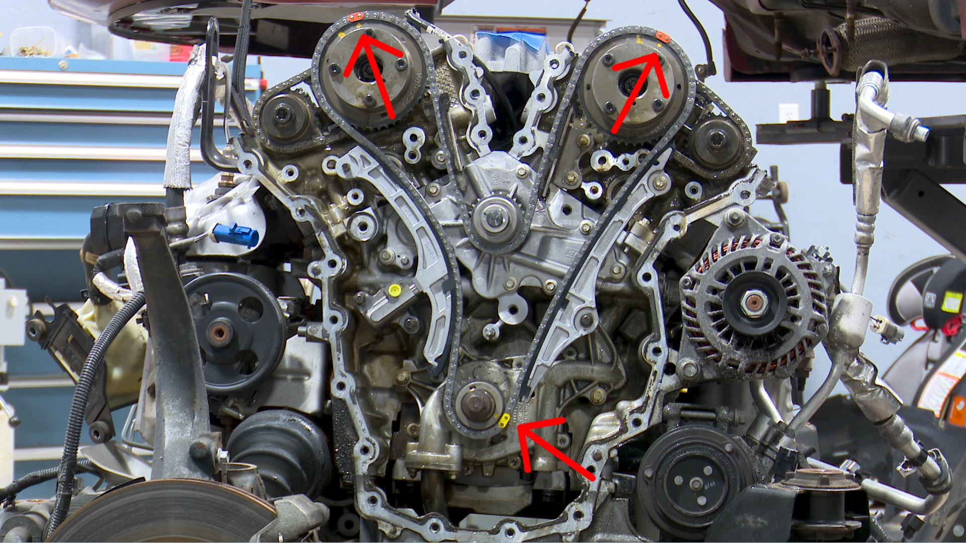
Watch this stage ▶ 14:50Full installation sequence ↓
Final recheck
After the rotation described in the guide, recheck with the camshaft holding tools. Their fit is the check shown here; the colored links do not return to their installation positions.
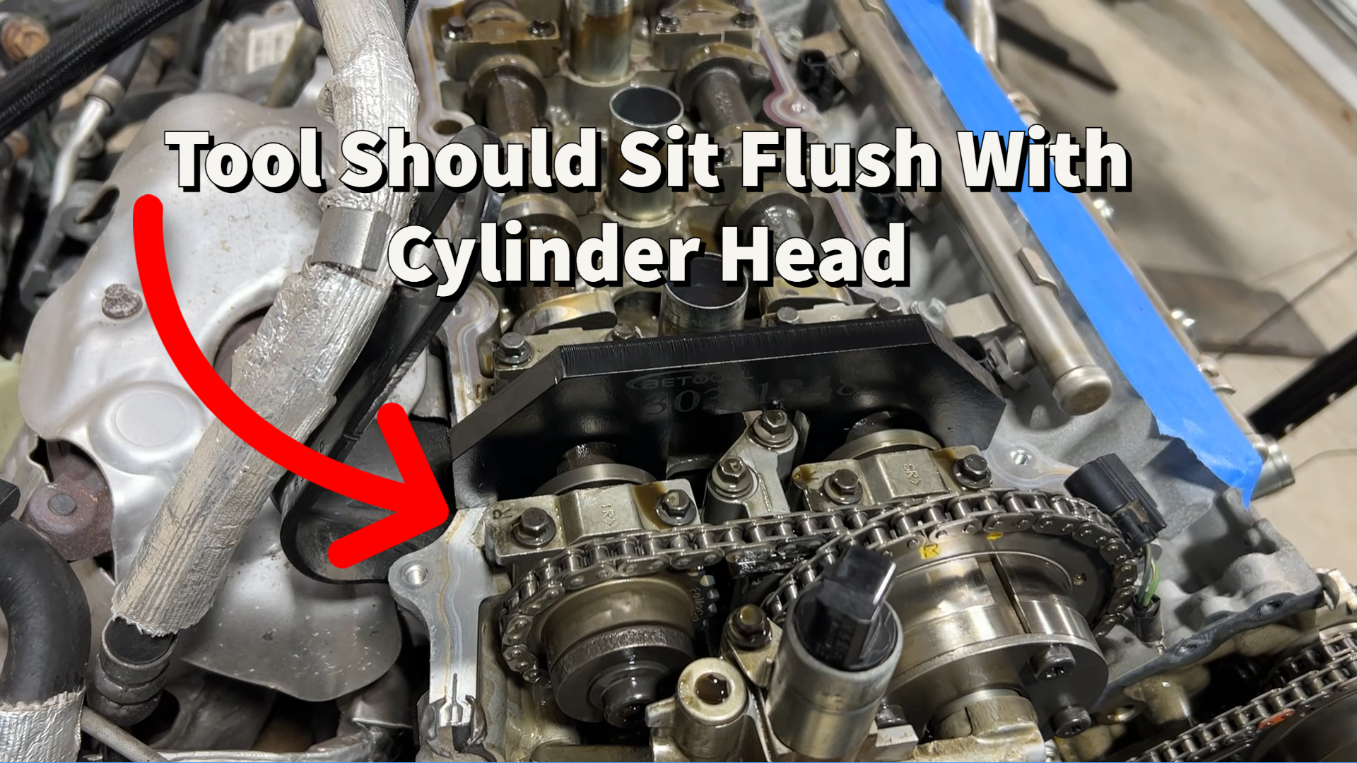
Watch the setup and recheck ▶ 19:32Full recheck sequence ↓
Which vehicles use this 3.5L engine family?
Demonstrated vehicle: 2010 Ford Fusion · 3.5L V6
This job began with an internal water-pump leak that contaminated the oil. Mike replaces the pump, primary timing chain, guides and tensioner. The primary chain is replaced as part of the pump repair; the job did not begin as a diagnosed chain-stretch repair.
What the demonstration covers: primary-chain removal, pump replacement, alignment and the holding-tool recheck. Secondary-chain replacement is outside this job’s scope. The engine is already out of the vehicle and the timing system exposed.
How this compares with the other vehicles
- 2010 Fusion 3.5L: identified in the video and confirmed by GoTech. Build-specific parts, access, fluids and current specifications still come from vehicle-specific service information.
- Other years and vehicles in the table: engine-family availability is sourced; identical access steps, parts and fastener specifications have not been established.
- Later Ti-VCT and turbo variants: separate timing-system comparison required. See the variant notes below.
Ford’s 2010 Fusion owner’s manual confirms the 3.5L engine option. It is an identification reference, not the timing-chain workshop procedure.
The early, naturally aspirated, transverse 3.5L family was offered in the vehicles below. Select the listed engine and trim; other engines were available in some of these models.
| Vehicle | Years | Engine / trim to check |
|---|---|---|
| Ford Fusion Sport | 2010–2012 | 3.5L Sport only. The 2010 Fusion is the reference demonstration; other years need procedure comparison. |
| Ford Edge | 2007–2010 | Early non-turbo 3.5L. |
| Lincoln MKX | 2007–2010 | 3.5L; later 3.7L versions are outside this list. |
| Lincoln MKZ | 2007–2012 | 3.5L gasoline model; exclude Hybrid. |
| Ford Taurus | 2008–2012 | Non-SHO, non-turbo 3.5L only. |
| Ford Taurus X | 2008–2009 | 3.5L wagon/crossover; not the earlier Freestyle 3.0L. |
| Ford Flex | 2009–2012 | Non-EcoBoost 3.5L only. |
| Mercury Sable | 2008–2009 | 3.5L generation; not older 3.0L Sable. |
| Mazda CX-9 | 2007 | 3.5L MZI; 2008 changes to 3.7L. |
The demonstrated vehicle is a 2010 Fusion 3.5L. The other entries establish engine-family availability; access, chain design, parts and specifications still require application-specific comparison.
Vehicle sources and research scope
Researched October 1, 2026 using manufacturer manuals, technical documents and the cited equipment coverage chart. Grouping these vehicles into the early engine family is an editorial assessment, not a technician sign-off on procedure compatibility.
- Ford Fusion Sport, 2010–2012: Source 1 · Source 2
- Ford Edge, 2007–2010: Source 1 · Source 2 · Source 3
- Lincoln MKX, 2007–2010: Source 1 · Source 2
- Lincoln MKZ, 2007–2012: Source 1 · Source 2
- Ford Taurus, 2008–2012: Source 1 · Source 2 · Source 3
- Ford Taurus X, 2008–2009: Source 1 · Source 2
- Ford Flex, 2009–2012: Source 1 · Source 2 · Source 3
- Mercury Sable, 2008–2009: Source 1 · Source 2 · Source 3
- Mazda CX-9, 2007: Source 1 · Source 2
Later 3.5L Ti-VCT engines and other variants
These later non-turbo applications have a related 3.5L engine, but need a separate comparison before using this guide:
- Ford Edge, 2011–2018: naturally aspirated 3.5L Ti-VCT. Source 1 · Source 2
- Ford Explorer, 2011–2019: naturally aspirated 3.5L Ti-VCT. Source 1 · Source 2
- Ford Flex, 2013–2019: naturally aspirated 3.5L Ti-VCT. Source 1 · Source 2
- Ford Taurus, 2013–2019: naturally aspirated 3.5L Ti-VCT. Source 1 · Source 2
EcoBoost/turbo engines, 3.7L engines and longitudinal truck/van installations are outside the application list above. Cloyes explains the chain, phaser and water-pump variations.
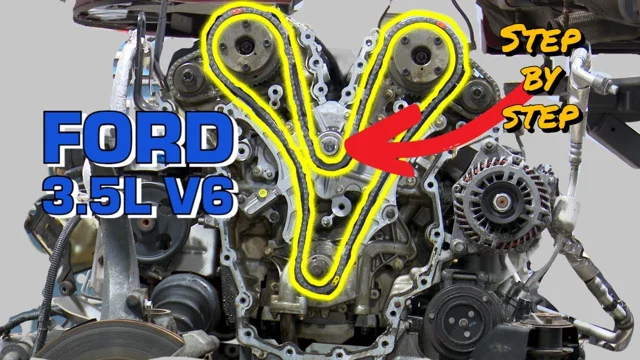
Video loads only when you choose to play.
Tools and preparation
Mike starts with the engine out of the vehicle and the timing system exposed. Engine removal and timing-cover access are not demonstrated here. Plan that work using service information for your exact vehicle.
- Vehicle-specific service information. Have the access, support, reassembly, fluid-service and specification instructions for your exact application. Those complete procedures are not supplied here.
- Camshaft holding tools. The guide uses them during timing setup and the final recheck. Confirm the required tool against your engine. OTC’s Ford 303-1248 reference helps identify the tool type.
- Torque and angle measurement. The source includes inch-pound tightening values and an additional angle stage. Prepare suitable measuring tools and verify the values in current service information.
- Mark visibility and component inspection. The source mentions a paint marker, guide inspection, sealing-surface inspection and VVT-housing O-rings. Review these steps before ordering parts; this is not a complete parts list.
- If reusing the tensioner. Read the source’s reset step first; it calls for a soft-jawed vise and a suitable locking pin.
Camshaft holding tool set linked in the original guide ↗Affiliate link: GoTech may earn a commission. Confirm fit before purchasing.
Specifications below belong to the 2010 Fusion 3.5L demonstration. Confirm them for your exact application.
Timing Chain Removal
Follow service information to remove the engine timing cover to gain access to the timing chain.
Rotate the crankshaft and align the mark on the crankshaft sprocket to around the 4 o'clock position ↗ 2:23
Enlarge illustration 1Check that the timing marks on the camshaft pulleys are in the correct location as pictured below ↗ 3:28
If marks are not visible, turn the crankshaft an additional 360 degrees
Enlarge illustration 2Install the camshaft holding tools to lock the camshafts and verify the correct engine timing ↗ 3:47
Remove the VVT housing assembly on both banks ↗ 6:04
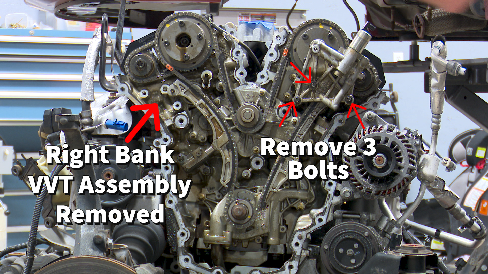 Enlarge illustration 3
Remove the 2 timing chain tensioner bolts and remove the timing chain tensioner ↗ 6:29
Remove the two larger timing chain guides ↗ 6:59
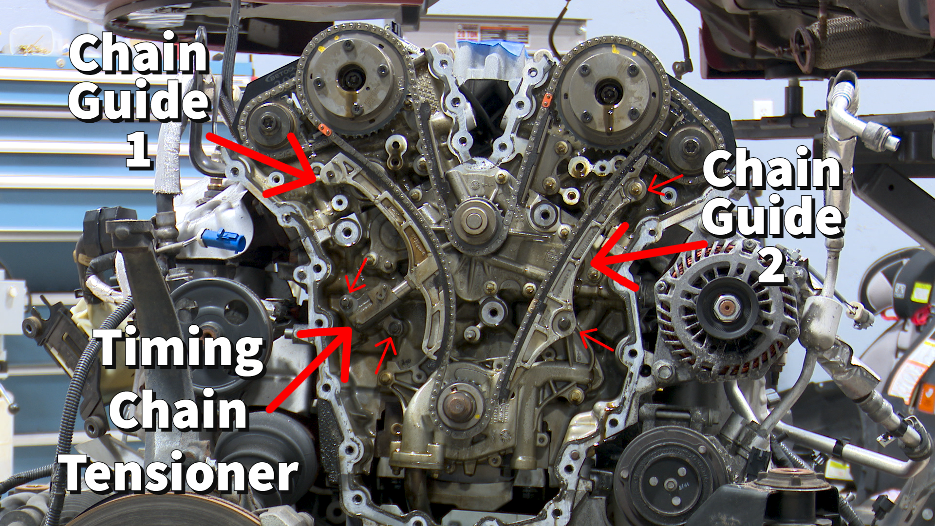 Enlarge illustration 4
Remove the timing chain
Water Pump Replacement
Remove the 8 bolts that attach the water pump to the engine block ↗ 8:38
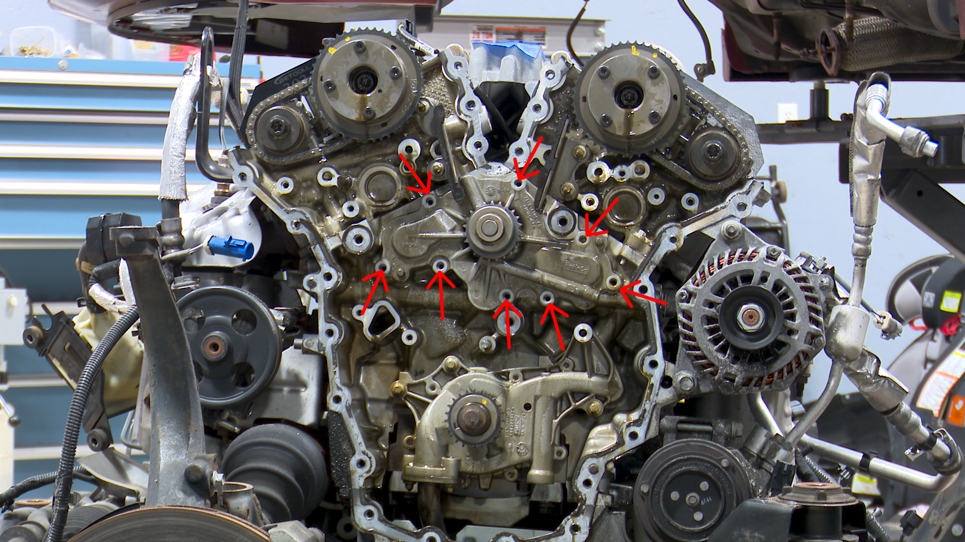 Enlarge illustration 5
Remove the lower bolt and loosen the upper bolt on the right bank smaller chain guide. Swing the chain guide out of the way and remove the water pump ↗ 10:10
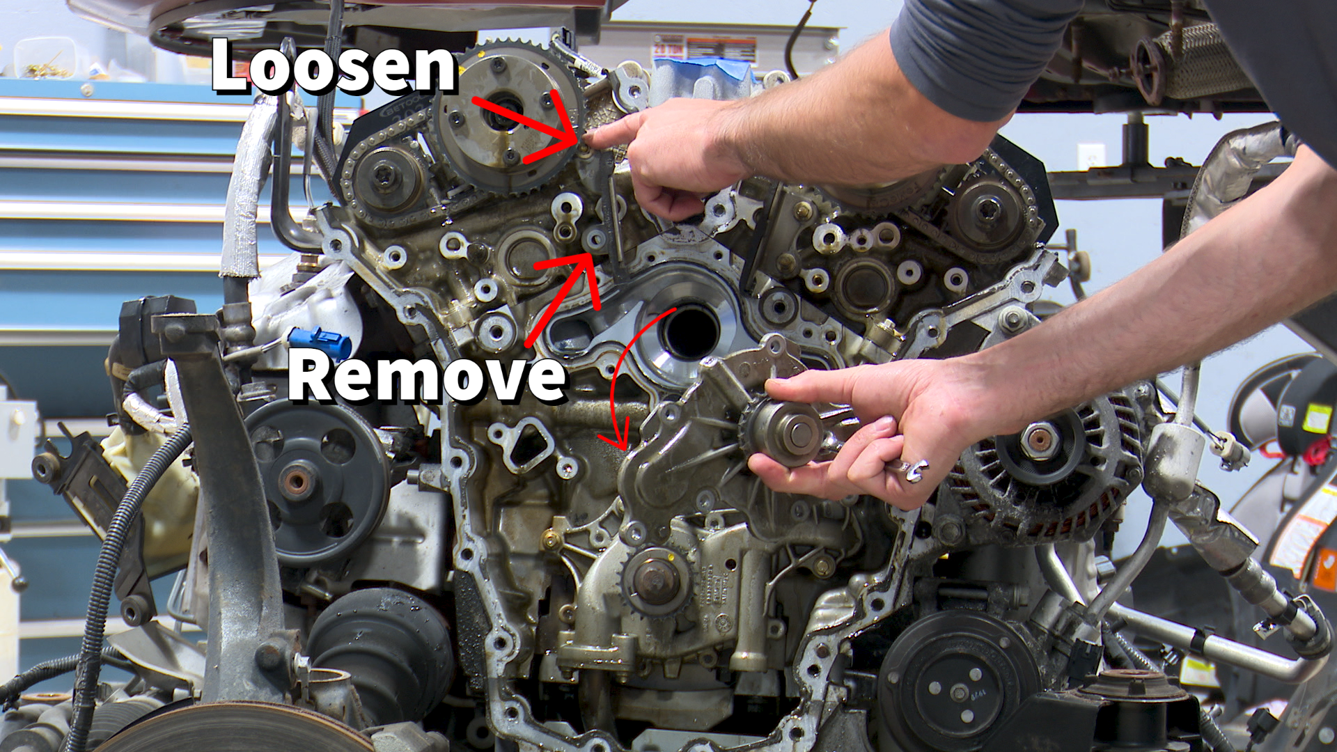 Enlarge illustration 6
Clean and inspect the water pump sealing surface
Install the new water pump and the 8 bolts. Tighten the bolts in two stages using the sequence below ↗ 11:08
Stage 1: tighten to 89 inch pounds
Stage 2: tighten an additional 45 degrees
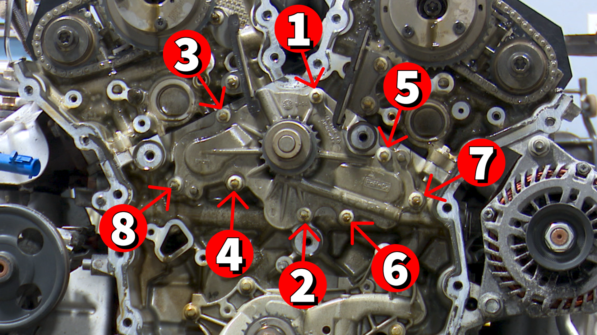 Enlarge illustration 7
Timing Chain Installation
Inspect timing chain guides and replace all guides that show signs of wear
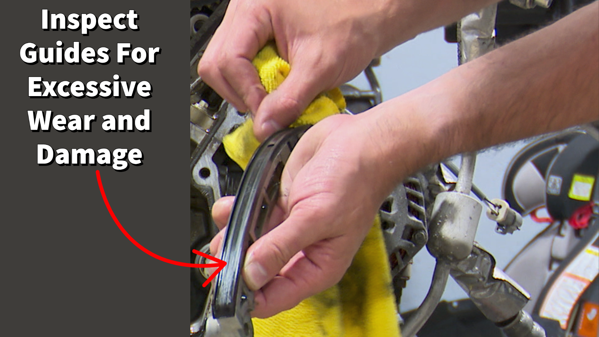 Enlarge illustration 8
Install the camshaft holding tools to lock the camshafts in place and to set the camshaft timing for chain installation
Install the timing chain aligning the two identical colored links with the camshaft sprocket timing marks and the odd colored link with the crankshaft sprocket timing mark ↗ 14:50
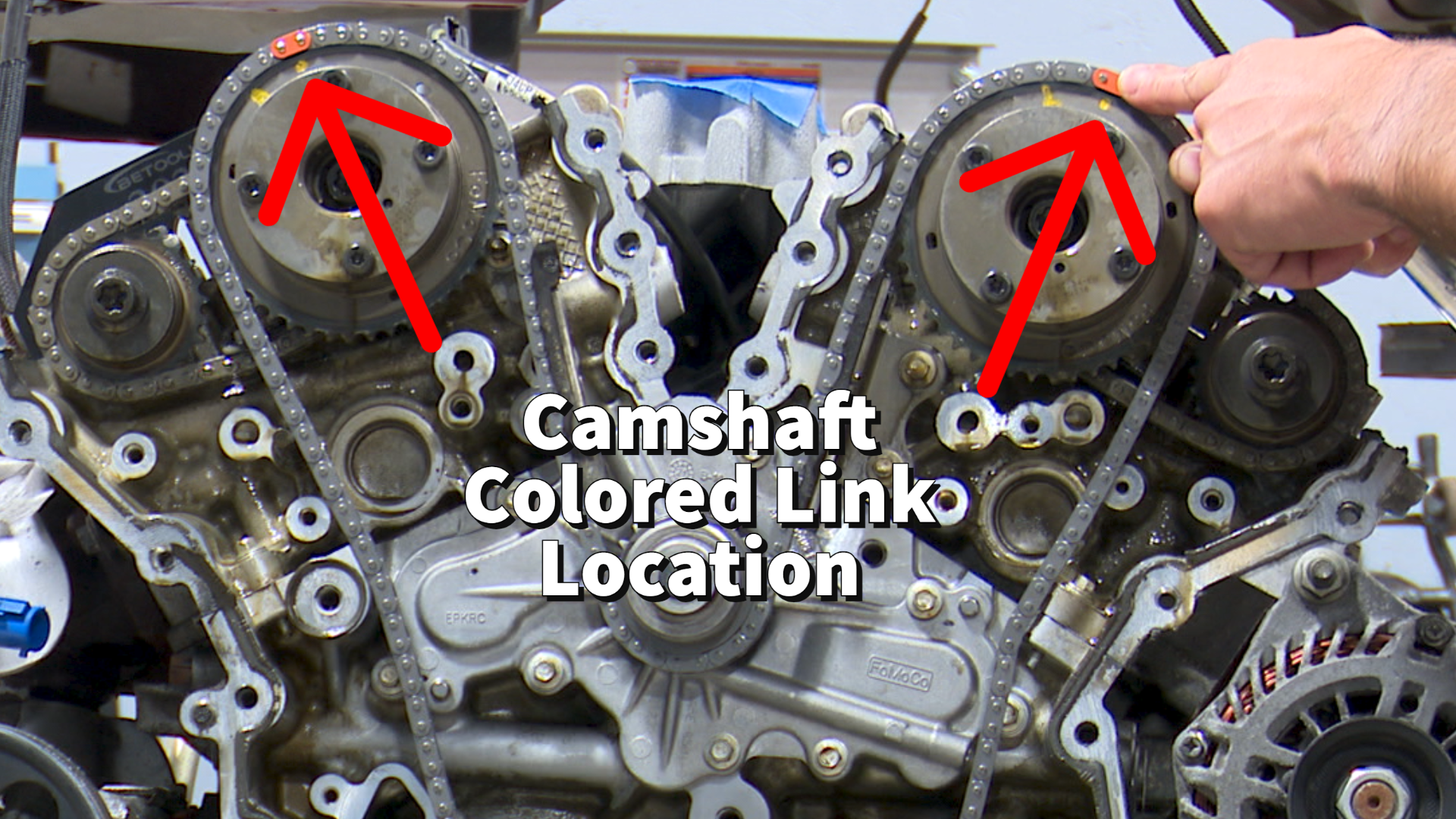 Enlarge illustration 9
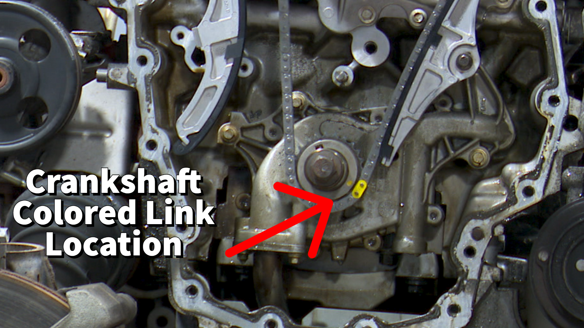 Enlarge illustration 10
Reinstall timing chain guides and torque bolts to 89 inch pounds ↗ 16:42
Install timing chain tensioner and torque bolts to 89 inch pounds ↗ 18:16
Double check that timing chain marks are lined up and the chain is seated correctly. If ok pull the pin on the timing chain tensioner ↗ 19:25
Enlarge illustration 11Remove camshaft holding tools and rotate the crankshaft around two complete revolutions ↗ 20:40
Recheck the engine timing by reinstalling camshaft holding tools ↗ 21:25
Enlarge illustration 12Reinstall the VVT housings and torque bolts to 89 inch pounds using the sequences below
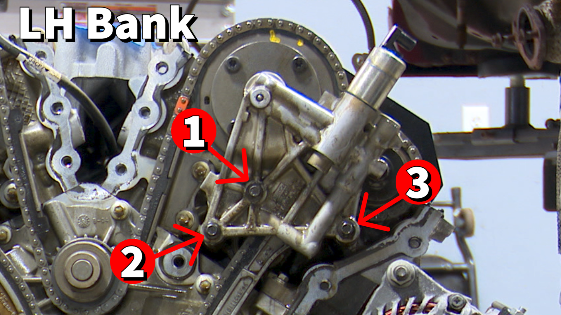 Enlarge illustration 13
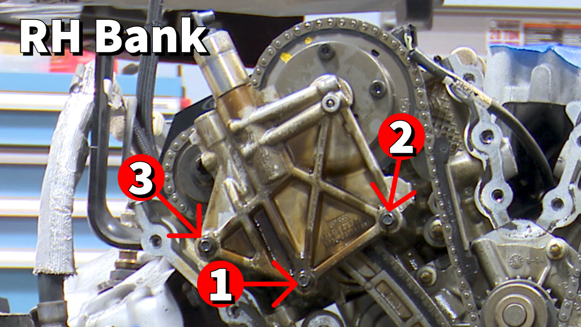 Enlarge illustration 14
Reverse procedure to reinstall timing chain cover and engine components
About this guide
Guide by GoTech Tech · Original video by Mike. Originally published September 8, 2022; editorial update October 1, 2026. Mike’s notes draw on the original demonstration, with chapter links so you can watch each observation in context.
Current source and limits
The original video identifies this demonstration as a 2010 Ford Fusion with the 3.5L engine. Its automatic captions support the job context and Mike’s practical observations. Current application-specific specifications, compatibility with other vehicles and a completed return-to-service result have not been independently verified here.
Installation alignment and the later timing recheck are separate stages. Keep each diagram and observation with its stage.
Find your next repair guide
Browse original GoTech instructions, or search the library by vehicle, component or trouble code.